
12 to 250V converter circuit diagram electronic project
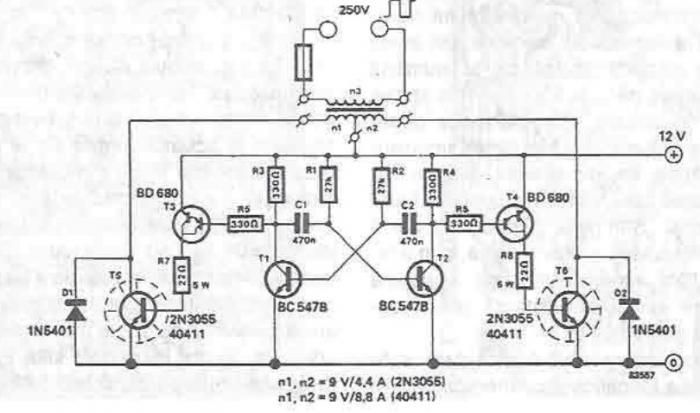
This portable 12V to 250V converter circuit is particularly useful for applications that require high voltage from a low voltage source, such as a car battery. The astable multivibrator configuration, utilizing T1 and T2, is critical for generating the necessary square wave signal to drive the transformer. The transformer (Tr) steps up the voltage from the secondary winding, which is crucial for achieving the desired output voltage.
The choice of output transistors significantly impacts the circuit's performance. Using RCA 411 transistors allows for a higher power output of 180 watts, suitable for more demanding applications. In contrast, the 2N3055 transistors, while still effective, limit the output to around 90 watts, which may be sufficient for lighter loads. The push-pull arrangement of the output stage ensures that both halves of the transformer are utilized efficiently, maximizing the power transfer.
Thermal management is a critical consideration in this design. The output transistors must be adequately cooled due to their operation at saturation, which generates substantial heat. Properly sized heat sinks are essential to prevent thermal runaway and ensure reliable operation over extended periods.
The inherent nature of the square wave output presents challenges for certain applications. The lack of a voltage regulator means that the output voltage can vary significantly based on the load connected to the circuit. This variability can lead to performance issues in sensitive electronic devices that require stable voltage levels. Therefore, while the circuit is straightforward and efficient, it is recommended for applications where high voltage is needed without the stringent requirements for voltage regulation.A very simple portable 12 to 250V converter can be designed using this circuit diagram. This 12 to 250V converter is designed for portable use with a 12 V car battery. A built astabil multivibrator T1 and T2 generates a rectangular wave at a frequency of 50 Hz. As T1 and T2 drive alternative exit stage system also works in "push-pull". When T1 lea d by passing a current T3: T5 and that it engages the latter transistor connects to a half battery of 12 V secondary winding of the transformer Tr When T2 network drive, T6 transistor coupled to the battery the other half of the network adapter. If it is used for output stages 40 411 RCA transistors, the current through secondary winding can be up to 10 A, giving a power output of 180 watts.
If you use 2N3055 transistors, power output will be about 90 watts. Since the output transistors are driven to saturation, they have very high mounted radiators. Although circuit is simple construction and has high efficiency disadvantage is rectangular output voltage which, in the absence of a regulator is dependent on task: small loads, the output voltage is 250 V ac (not working properly for the engine speed control, light dimmers, televisions, hi-fi equipment. 🔗 External reference
Related Circuits

An automatic electric furnace temperature controller is illustrated. The closed circuit consists of a temperature detection output control loop; as the temperature increases, the output voltage rises until it reaches a preset temperature value, at which point the output...
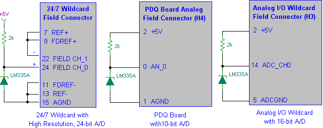
Interfacing the LM335A temperature sensor with A/D converters involves measuring temperature using the LM35 and LM335A sensors alongside the 9S12 HCS12 microcontroller. This process includes analyzing both calibrated and uncalibrated temperature errors of integrated circuit temperature sensors. The LM335A is...
This file is copyrighted. The individual who uploaded this work and first used it in licensing holds the rights. The provided information indicates that the file is protected by copyright, with the rights belonging to the individual who initially uploaded...
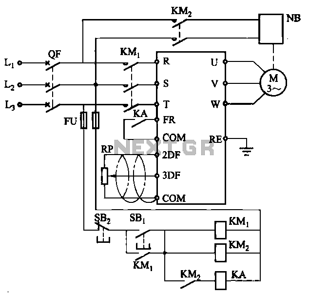
Electromagnetic brake motors consist of a motor and an electromagnetic brake, forming a standard assembly. The circuit diagram is provided. In this configuration, FR represents the forward run and stop command terminal, while the intermediate relay KA is employed...
Multi-spark ignition is very useful especially in the case of startings at low temperature and at low rpm range. Basic idea, is to apply to spark plugs instead of only one spark, a spark-burst having big energy. In this...
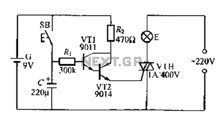
A delay circuit utilizing an electric lamp. Normally, the thyristor VTH remains off, and the lamp E does not illuminate. The lamp turns on when needed, controlled by the FSH, with the VT1 and VT2 components forming a composite...
Warning: include(partials/cookie-banner.php): Failed to open stream: Permission denied in /var/www/html/nextgr/view-circuit.php on line 713
Warning: include(): Failed opening 'partials/cookie-banner.php' for inclusion (include_path='.:/usr/share/php') in /var/www/html/nextgr/view-circuit.php on line 713