
AD594 to 597 basic application circuit b

An automatic electric furnace temperature controller operates within a closed-loop system designed to maintain the desired temperature efficiently. The system begins with a thermocouple (TC) that senses the current temperature of the furnace. The TC generates a voltage output proportional to the temperature, which is fed into an integrated circuit (IC1). This circuit contains a differential amplifier that compares the sensed temperature against a predetermined setpoint.
As the furnace temperature rises, the output voltage from the TC increases. When this voltage reaches the setpoint, the output from the differential amplifier triggers a solid-state relay (VT), which disconnects the heating element (RL) from the power supply, effectively stopping the heating process. Conversely, if the temperature drops below the setpoint, the system re-engages the relay, allowing current to flow to the heating element and thus restarting the heating process.
The controller features hysteresis settings that help prevent rapid cycling of the heating element. This is achieved by connecting a resistor (R) to the input and output pins of the differential amplifier. The value of this resistor is critical; a lower resistance increases the hysteresis, providing a wider temperature band before the relay toggles between on and off states. This design choice enhances the stability of the temperature control by reducing the frequency of activation and deactivation.
Additionally, the AD594/595 model includes a zero offset circuit, although it is not employed in this particular application. Alarm pins are incorporated into the design to provide visual or auditory feedback regarding the system's operational status. An open collector transistor allows the controller to drive an indicator LED or small relay, providing a clear indication of whether the heating element is active.
The use of a diode (VD1) serves as a visual cue for the user, illuminating when the heating element is engaged. This comprehensive design ensures that the electric furnace maintains the desired temperature efficiently while providing necessary feedback to the user. Automatic electric furnace temperature controller shown. The closed circuit is formed from a temperature detection output control loop; the temperature rises, the output voltag e increases when the voltage increases to a preset temperature value, the output stop, stop heating; trans, the temperature is lowered, when reduced to the pre when the set temperature, and automatically starts heating. TC thermocouple directly connected to IC1 s O, ? feet, sending internal differential amplifier, the output from a foot, driven by solid state relay vs VT conduction, plus hot wires RL ohmic heating, when heated to a preset temperature, output is stopped.
pin input and output hysteresis setting, connected to a pin through resistor R to achieve, the smaller the resistance value, the greater the hysteresis. Controlling the temperature of the high and low foot by pressing decisions relations pin voltage and temperature, TC between as shown in Table 1-3.
AD594/595 is also designed with zero offset circuit (not used here). ?, ? pin alarm, indicating the output of the internal as c, e very open transistor can directly drive LED or small relays, access here VD1 as the working lights for indicating the start and stop on heating.
Related Circuits
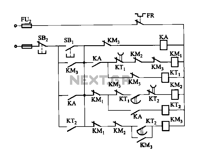
Figure 3-118 illustrates an automatic acceleration control circuit. This circuit employs a male contactor time relay, enabling the motor to start automatically at a low speed before transitioning to high-speed operation. The automatic acceleration control circuit depicted in Figure 3-118...
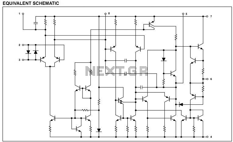
NE5532DR absolute maximum ratings: (1) Supply voltage: VCC+ 22 V; VCC-: -22 V; (2) Input voltage, either input VCC ±; (3) Input current: ±10 mA; (4) Duration of output short circuit: Unlimited; (5) Package thermal impedance, JA: D package...

This simple circuit consists of a transformer, two diodes, a capacitor, and an ammeter. To charge a battery, connect the positive and negative terminals of the circuit to the corresponding terminals of the battery. When the battery is not...
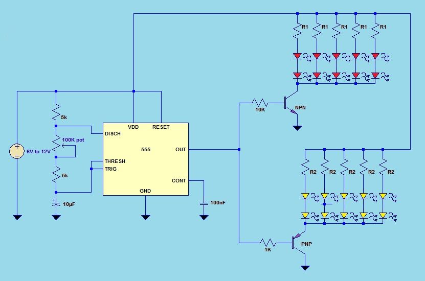
This project utilizes a 555 timer integrated circuit (IC) in an 8-pin configuration to control multiple LEDs. It is designed for quick assembly and allows for the adjustment of timing functions. The circuit employs a 555 timer in astable mode,...
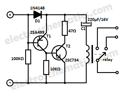
Protect your equipment with this compact 12V time delay relay circuit. The SMPS-based power supply of modern electronic devices is susceptible to voltage spikes. This 12V time delay relay circuit is designed to safeguard sensitive electronic devices by providing a...

Automatic electronic refrigerator deodorant sterilization circuit The automatic electronic refrigerator deodorant sterilization circuit is designed to eliminate odors and sterilize the interior of a refrigerator. This circuit typically employs a combination of sensors, microcontrollers, and sterilization techniques to achieve effective...