
Electromagnetic brake motor frequency control circuit
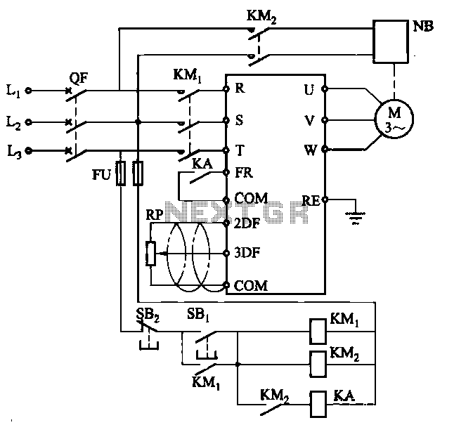
The electromagnetic brake motor circuit operates by integrating a standard motor with an electromagnetic brake system, which ensures that the motor can stop quickly and hold its position when not in operation. The circuit involves several key components, including the motor, the electromagnetic brake, the forward run (FR) command terminal, and an intermediate relay (KA).
The forward run command terminal (FR) serves as the input for initiating the motor's operation. When a signal is applied to this terminal, it activates the intermediate relay (KA), which in turn energizes the motor. The relay functions as a switch that can handle higher currents than the command terminal, ensuring safe and efficient operation.
The electromagnetic brake is designed to engage when the power to the motor is cut, providing immediate braking action. This feature is particularly advantageous in applications requiring rapid stops or where load holding is critical. The brake is typically powered by the same circuit and is released when the motor is energized, allowing for smooth operation during forward runs.
The circuit may also include additional safety features such as overload protection devices and limit switches, which can prevent the motor from operating under unsafe conditions. These components are essential for maintaining the integrity of the system and ensuring reliable performance over time.
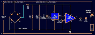
Overall, the integration of the electromagnetic brake with the motor and the use of an intermediate relay for control creates a robust system capable of handling various operational demands in industrial and commercial applications.Electromagnetic brake motors from the motor and electromagnetic brake NB ordinary composition. Circuit is shown. Figure, FR is the forward run and stop command terminal; intermediate relay KA is used to control the motor started.
Related Circuits
Construct a low-power FM transmitter using surface-mount devices (SMD) that can be received by a standard FM radio. The proposed low-power FM transmitter circuit utilizes surface-mount devices (SMD) to achieve compactness and efficiency. The primary components of the circuit include...
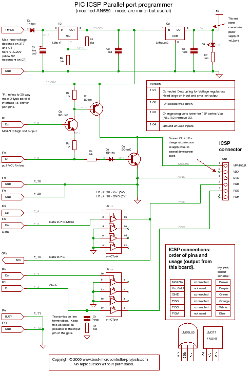
A PIC programmer circuit that operates using long cables from a PC to the programmer. The PIC programmer circuit is designed to facilitate the programming of PIC microcontrollers via a connection to a personal computer (PC) using extended cabling. This...
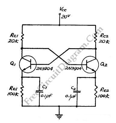
This flip-flop circuit functions as a free-running astable multivibrator, where the bases and collectors of both emitter-biased transistors are directly coupled. The switching action is facilitated by a capacitor in each emitter circuit, resulting in the generation of triangle...
Computers often experience overheating due to prolonged use or high ambient temperatures, making temperature controllers essential. Accurate temperature measurement is necessary to ensure that the computer operates within a safe temperature range. A circuit diagram for a simple temperature...

Figure 1-30 illustrates an example of an output capacitor-less (OCL) power amplifier circuit, which can be analyzed as follows: In this circuit, transistors VTi and VTz form a single-ended input and a differential input single-ended output amplifier configuration. The...
Is the battery depleted, or is there an issue with the device? This question often arises when a battery-operated device, such as a Walkman, fails to power on. Before seeking professional repair services, it is advisable to first test...
Warning: include(partials/cookie-banner.php): Failed to open stream: Permission denied in /var/www/html/nextgr/view-circuit.php on line 713
Warning: include(): Failed opening 'partials/cookie-banner.php' for inclusion (include_path='.:/usr/share/php') in /var/www/html/nextgr/view-circuit.php on line 713