
12 volt car battery monitor
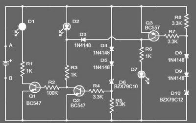
The circuit employs a series of transistors and light-emitting diodes (LEDs) to provide visual feedback regarding the battery's voltage status. The design utilizes three NPN transistors (Q1, Q2, Q3) configured as switches to control the respective LEDs (D1, D2, D3).
When the battery voltage falls below 11.5V, the base of transistor Q1 receives sufficient voltage, turning it on and allowing current to flow through LED D1, which indicates a low battery condition. This serves as a warning to the user that the battery needs recharging.
As the voltage rises to between 11.5V and 13.5V, the voltage at the base of transistor Q2 also becomes adequate to turn it on, activating LED D2. This state indicates that the battery is in a moderately charged state, which is acceptable for normal operation.
Once the battery voltage exceeds 13.5V, transistor Q3 is activated, allowing current to pass through LED D3. This indicates that the battery is fully charged and operating within a healthy voltage range.
The circuit is powered by a 12V source connected between terminals A and B, which provides the necessary voltage for operation. The design allows for flexibility in the choice of LEDs, enabling the use of different colors for each voltage range, enhancing visual differentiation for the user.
Overall, this battery monitoring circuit provides a simple yet effective method for assessing the state of charge of a car battery, using straightforward components and clear visual indicators.This circuit can be used to monitor the voltage level of a car battery. When the battery voltage is 11. 5V or less the transistor Q1 is on and D1 glowing. When LED battery voltage is between 11. 5 to 13. 5 V, the transistor Q2 is on and the glowing LED D2. When the battery voltage is above 13. 5 V, the transistor Q3 is on and the LED D3 will be brigh t. The 12 volt control can be connected between terminals A and B and for the convenience of using LEDs of different colors. 🔗 External reference
Related Circuits

This digital voltmeter is ideal for measuring the output voltage of a DC power supply. It features a 3.5-digit LED display with a negative voltage indicator. The device measures DC voltages from 0 to 199.9V with a resolution of...

A 2x22 W car audio amplifier circuit utilizes the TDA1558, a monolithic integrated class-B output power amplifier that includes four 11 W single-ended amplifiers or two 22 W bridge-tied load (BTL) amplifiers. The TDA1558 is designed to drive speakers in...

Application of the High Power LED Driver SP7652 with an Analog 0V-to-10V dimmer. Electrical Requirements: Input Voltage of 5.5V to 28V, Output Voltage VF of LED, Output Current ranging from 0 to 6A. This circuit is designed to provide...
Voltage inverter circuit design electronic project using few electronic components The voltage inverter circuit is a fundamental electronic project that converts direct current (DC) to alternating current (AC). This circuit is particularly useful in applications where AC voltage is required...
The LM317T is an adjustable three-terminal positive voltage regulator capable of supplying more than 1.5 amps with an output range of 1.25 to 37 volts. The device features built-in current limiting and thermal shutdown, making it robust against failure....
This FM radio-controlled anti-theft alarm can be used with any vehicle having a 6- to 12-volt DC supply system. The mini VHF, FM transmitter is fitted in the vehicle at night when it is parked in the car porch...