
LM317T Variable Voltage Regulator
The LM317T voltage regulator is designed for versatility in various electronic applications, allowing for adjustable output voltages tailored to specific requirements. The device operates by adjusting the resistive divider formed by R1 and R2, which sets the output voltage based on the feedback it receives. The internal architecture of the LM317T includes a reference voltage source, an error amplifier, and a pass transistor, which collectively regulate the output voltage.
In practical applications, the use of capacitors is critical. The output capacitor (1 µF tantalum or 25 µF electrolytic) stabilizes the voltage and improves load transient response, ensuring minimal voltage fluctuations during sudden load changes. The input capacitor (0.1 µF tantalum) serves to filter high-frequency noise, especially important in designs where the regulator is located far from the power supply filter, minimizing the risk of oscillation or instability.
The selection of R1 and R2 is essential for achieving the desired output voltage. For example, using a 120-ohm resistor for R1 ensures the regulator operates within its specified parameters under minimum load conditions. The calculated resistance for R2 can be adjusted according to the desired output voltage using the formula provided, ensuring that the regulator remains efficient and stable.
Safety features, such as the thermal shutdown and current limiting, protect the LM317T from damage due to excessive load conditions or overheating. In scenarios where reverse voltage might occur, the addition of a protection diode across the input and output terminals is a prudent design choice, safeguarding the regulator from potential damage.
Overall, the LM317T is a robust and reliable component for voltage regulation in electronic circuits, providing flexibility and stability for various applications, from simple power supplies to more complex electronic devices.The LM317T is a adjustable 3 terminal positive voltage regulator capable of supplying in excess of 1. 5 amps over an output range of 1. 25 to 37 volts. The device also has built in current limiting and thermal shutdown which makes it essentially blow-out proof.
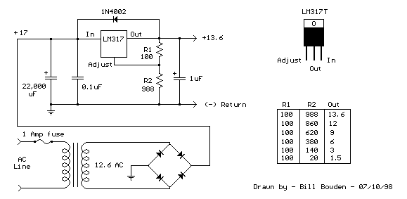
Output voltage is set by two resistors R1 and R2 connected as shown below. The voltage ac ross R1 is a constant 1. 25 volts and the adjustment terminal current is less than 100uA. The output voltage can be closely approximated from Vout=1. 25 * (1+(R2/R1) which ignores the adjustment terminal current but will be close if the current through R1 and R2 is many times greater. A minimum load of about 10mA is required, so the value for R1 can be selected to drop 1. 25 volts at 10mA or 120 ohms. Something less than 120 ohms can be used to insure the minimum current is greater than 10mA. The example below shows a LM317 used as 13. 6 volt regulator. The 988 ohm resistor for R2 can be obtained with a standard 910 and 75 ohm in series. When power is shut off to the regulator the output voltage should fall faster than the input. In case it doesn`t, a diode can be connected across the input/output terminals to protect the regulator from possible reverse voltages.
A 1uF tantalum or 25uF electrolytic capacitor across the output improves transient response and a small 0. 1uF tantalum capacitor is recommended across the input if the regulator is located an appreciable distance from the power supply filter.
The power transformer should be large enough so that the regulator input voltage remains 3 volts above the output at full load, or 16. 6 volts for a 13. 6 volt output. 🔗 External reference
Related Circuits
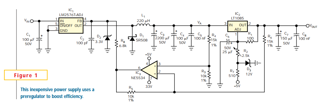
Linear regulators are easy to implement and have better noise and drift characteristics than switching approaches. Their largest disadvantage is inefficiency: excess energy dissipated as heat. Several well-known techniques are available to minimize the input-to-output voltage across a linear...
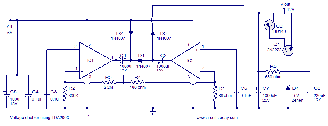
A reliable voltage converter circuit that operates between 6 to 12 volts, utilizing the audio amplifier IC TDA 2003. This voltage doubler circuit can be assembled on a Vero board. The voltage converter circuit designed with the TDA 2003 audio...
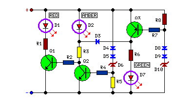
This circuit monitors battery voltage and features a three-LED display. By connecting this circuit to the battery of a vehicle, users can easily determine the approximate voltage at a glance. The battery voltage monitoring circuit utilizes a simple yet effective...
This continuity tester circuit allows for the examination of PCB track failures without the need to visually inspect the routing of the tracks, which can often be frustrating. The continuity tester circuit is designed to facilitate the detection of faults...
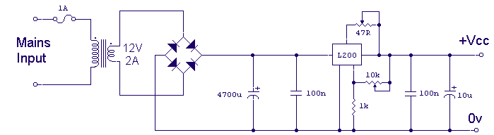
Using the versatile L200 voltage regulator, this power supply has independent voltage and current limits. The mains transformer has a 12volt, 2 amp rated secondary, the primary winding should equal the electricity supply in your country, which is 240V...
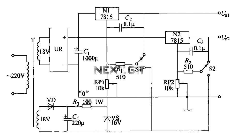
An adjustable dual voltage power supply circuit is presented, suitable for frequent experimental use. The current output does not exceed 1A, and both voltage outputs are adjustable. The circuit utilizes N1, N2, and 78 series three-terminal voltage regulator integrated...