
12V/1.5A Residential AlarmCircuit
The alarm circuit operates on a regulated 12V power supply, ensuring stable performance across various conditions. The 1.5A rating allows sufficient current to power all components, including the siren and any additional peripherals that may be connected.
A key feature of this circuit is the delay circuit, which provides a grace period for users to disarm the system after activation. This is particularly useful in residential settings where false alarms can be triggered by accidental activation. The delay can be adjusted to suit user preferences or specific security needs.
The 24-hour panic circuit is another critical component, allowing users to trigger an alarm at any time, regardless of the system's armed status. This feature enhances personal safety, as it enables immediate alerting in emergency situations.
The built-in siren driver is designed to drive a siren or alarm sounder, producing an audible alert when the system is triggered. This driver is capable of handling various siren specifications, providing flexibility in alarm sound selection.
Alarm memory is incorporated into the circuit design, allowing the system to retain information about the last triggered event. This feature is beneficial for users to review alarm history and assess potential security breaches.
Remote arming station terminals facilitate the connection of external arming and disarming devices, providing users with the convenience of controlling the system from various locations within a property. This enhances usability and allows for quick responses to security events.
Finally, the arming inhibit feature prevents the system from being armed under certain conditions, such as when doors or windows are left open. This functionality is crucial for preventing false alarms and ensuring that the system is only activated when the premises are secure.
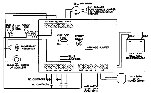
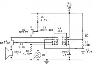
Overall, this alarm circuit is designed to provide robust security solutions for both residential and commercial applications, integrating multiple features that enhance usability, safety, and reliability.The following alarm circuit is designed with features which maybe suited for residential and commercial alarm system applications. It has 12V and 1. 5A regulated power supply. Furthermore, this residential alarm circuit also features such delay circuit, 24-hour panic circuit, built-in siren driver, alarm memory, remote arming station terminals and
arming inhibit. 🔗 External reference
Related Circuits
Have you ever seen the stairs to one of the upper stories in your house turn into a waterfall? Or maybe you've come home to find your aquarium fish trying to... The provided description suggests a scenario involving unexpected water...
The loop can be any type of hookup wire, with a maximum resistance of about 90K. Using very thin wire (40AWG, for example) will create a highly sensitive trip wire, but will reduce the distance it can be strung...
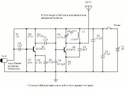
The following circuit illustrates a Wireless Car Alarm Circuit Schematic Diagram. Features include the ability to detect sounds within a 20-meter radius, a 1/16 wavelength antenna, and the capability to transmit radio signals up to 2 kilometers. Q1 serves...
Much of the focus on residential gateway designs has been on distributing communication connectivity within a home. However, to effectively distribute content, gateways must first possess a reliable WAN interface that provides access to cable modems, fixed broadband wireless,...
The following circuit illustrates a Sun Up Alarm Light Alarm Circuit Diagram. This circuit is based on the 555 Integrated Circuit (IC). Features include simplicity and cost-effectiveness. The Sun Up Alarm Light Alarm Circuit employs the 555 timer IC in...
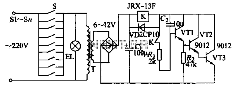
Pressing the button switch Sl-Sn activates the circuit, turning on the transformer T. The low-voltage alternating current from the secondary winding is directed to a bridge rectifier and a filter capacitor Ci, which produces a DC voltage. This voltage...