
High-rise residential walkway lighting control circuit
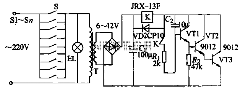
The circuit described operates as a self-latching relay system, which maintains the state of the output (lamp) after the initial activation. The transformer T steps down the mains voltage to a safer low-voltage AC level, which is then rectified by the bridge rectifier into DC voltage suitable for the relay and control circuitry. The filter capacitor Ci smooths out the rectified output, ensuring stable voltage levels.
The relay coils K are critical components that allow for the control of the lamp. When energized, they create a magnetic field that closes the normally open contacts and opens the normally closed contacts, thereby locking the system in an 'on' state. The interaction between capacitors C1 and C2 plays a vital role in controlling the timing and behavior of the circuit.
Transistor VT1 acts as a switch that responds to the voltage levels at its base. When the button is pressed, C1 charges quickly and provides the necessary base current to turn on VT1. This action enables the relay to remain activated even after the button is released, thanks to the voltage stored in C2. The design ensures that the lamp remains illuminated until the voltage across C2 drops below a certain threshold, allowing the relay to deactivate.
The discharge path through resistor Rz allows for a controlled release of voltage from C2, preventing abrupt changes that could damage the components or cause erratic behavior. This careful design consideration ensures reliability and longevity of the circuit.
Overall, this circuit provides a practical solution for applications requiring a momentary switch to control a persistent output, such as lighting systems, alarms, or other electronic devices where a temporary input should result in a sustained activation. Click the button switch Sl-Sn, lights that light, the power is turned on while the transformer T, the low-voltage alternating current through the secondary winding down of a br idge rectifier and filter capacitor Ci later, c1 Yam ended output a DC voltage, the voltage through relay coils K, normally open relay contacts connected to the resistor R]: C2 and tortoise pit these two branches vri applied to the transistor base and make VT1 with a forward bias. then. Composite pipe quickly saturated conduction, the relay group Zhen shearwaters current flows, the normally closed contacts well, forming self-locking.
Thus, even if SI release the button, the lamp is still lit. In the normally open contacts closed, while the other normally closed contact is broken open, the power to continue to charge through the relay winding cz, due rri turtle small base current, and the voltage across C2 can not be mutated, dichotoma witch aid potential which can slowly increased, so Cui following axis during this period. Clamor will continue to maintain hoodoo ridge; when c2 charging voltage winding to the release, since the relay winding ends little pressure; insufficient J maintain strong pull, then K off, lights off, Xie small boat pass through winding and grinding out.
c2 on the residual voltage through VT1 and rapid discharge circuit consisting of Rz is done to prepare for the next delay purposes,
Related Circuits
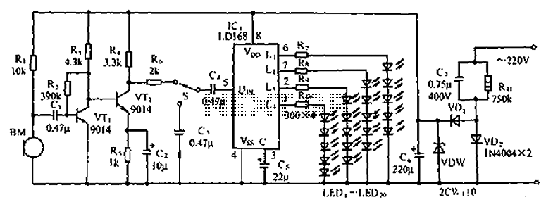
The circuit depicted in the figure involves the LD168, which functions as a sound level indicator for tape recorder speakers. It features four outputs capable of directly driving multiple light-emitting diodes. Additionally, the device can be activated by a...
The core of the circuit features an Arduino microprocessor, represented by the header pins on the left side of the circuit schematic. Two analog inputs, labeled 0 and 1, are connected to the emitter sides of TEMT6000 ambient light...
By utilizing logic chips, the behavior of a robot can be enhanced, allowing for the implementation of more complex algorithms. Logic chips, also known as logic gates or digital logic integrated circuits, are fundamental components in digital electronics that perform...
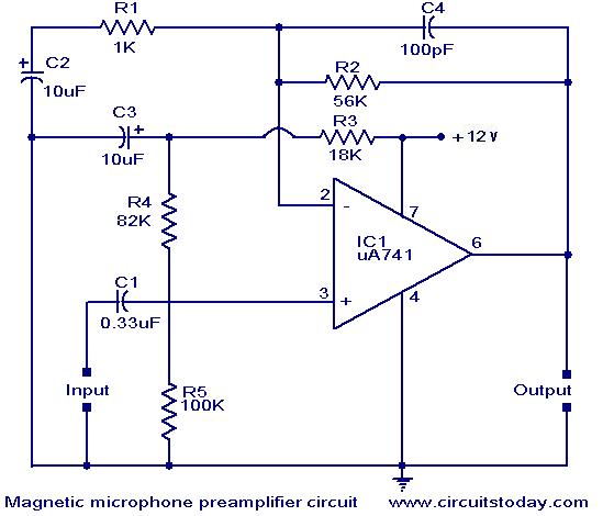
A preamplifier for magnetic pickups of record players is presented. The uA 741 is utilized as an AC-coupled non-inverting amplifier operating on a single supply. The amplifier gain is determined by the feedback components, where C2 manages the low-frequency...
General Diagram of Motor Controller Manual PDF Download. The motor controller is an essential component in various applications, including robotics, electric vehicles, and industrial machinery. It regulates the operation of electric motors by controlling parameters such as speed, direction, and...
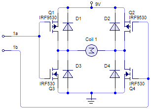
A bridge motor drive circuit is illustrated, featuring a driving stage composed of four transistors. The control circuit includes four terminals labeled A, B, C, and D, which facilitate the control of forward or reverse motor rotation. The control...
Warning: include(partials/cookie-banner.php): Failed to open stream: Permission denied in /var/www/html/nextgr/view-circuit.php on line 713
Warning: include(): Failed opening 'partials/cookie-banner.php' for inclusion (include_path='.:/usr/share/php') in /var/www/html/nextgr/view-circuit.php on line 713