
12V battery charger with 555
The charger design features a two-stage architecture that efficiently converts and regulates voltage for battery charging. The first stage employs a capacitive voltage doubler, utilizing a 555 timer integrated circuit (IC) to generate a square wave signal. This signal drives a pair of transistors configured as emitter followers, which are responsible for boosting the input voltage to a higher level. The voltage doubler circuit incorporates power resistors that are crucial for limiting the charging current to protect the batteries being charged.
In the second stage, a 7815 voltage regulator IC is implemented to ensure a stable output voltage of approximately 14.4V, suitable for charging gelled or absorbed glass mat (AGM) batteries. A diode is placed in series with the output of the regulator to prevent reverse current flow, which could damage the circuit, while also slightly reducing the output voltage. The design includes a cautionary note against leaving the charger connected to the battery for prolonged periods, as the output voltage is too high for trickle charging. For those who wish to use the charger in a trickle charging capacity, an additional diode can be added in series with the existing diode to reduce the output voltage further.
An LED indicator is integrated into the design to signal the charging status. The LED illuminates when the charging current exceeds 150mA, providing a visual cue that the charger is operational. The maximum charge current is designed to be around 400mA, making it suitable for small 12V lead-acid batteries with capacities ranging from 2 to 10 Ah.
An auxiliary output is also available, providing approximately 20V at no load, which decreases under load conditions. This output is particularly useful for charging 12V, 4Ah nickel-cadmium (NiCd) battery packs, which require a limited current without strict voltage regulation during the charging process.
Safety features are incorporated into the design, including overcurrent protection for the main charge output. In the event of a short circuit, the overcurrent protection mechanism will activate; however, it is advised to avoid shorting the output to prevent potential damage to the diodes. In contrast, shorting the auxiliary output will result in the fuse blowing, providing an additional layer of protection.
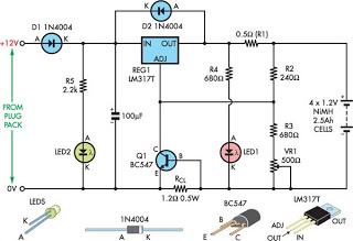
The physical construction of the charger involves a homemade aluminum sheet enclosure, employing a dead-bug construction style. This approach, while not aesthetically pleasing, ensures functionality. The long leads on the power resistors are a critical design choice, as they prevent unsoldering due to heat generated during operation. The transistors and voltage regulator are mounted directly to the enclosure, which acts as a heat sink, effectively dissipating heat and maintaining operational stability. The overall design has proven reliable over time, successfully charging various batteries for different applications.The charger consists of two stages: The first is a capacitive voltage doubler, which uses a 555 timer IC driving a pair of transistors connected as emitter followers, which in turn drive the voltage doubler proper. The doubler has power resistors built in, which limit the charging current. The second stage is a voltage regulator, using a 7815 regulator IC. Its output is applied to the battery via a diode, which prevents reverse current and also lowers the voltage a bit.
The resulting charge voltage is about 14.4V, which is fine for charging a gelled or AGM battery to full charge, but is too high as a trickle charger, so don't leave this charger permanently connected to a battery. If you would like to do just that, then add a second diode in series with D3! There is a LED connected as a charge indicator. It will light when the charge current is higher than about 150mA. The maximum charge current will be roughly 400mA. The charger described here is intended for charging small 12 Volt lead acid batteries, such as the gelled or AGM batteries of capacities between about 2 and 10 Ah, using a car's electrical system as power source, regardless of whether the car engine is running or not. There is an auxiliary output, that provides about 20V at no load (depending on input voltage), and comes down as the load increases.
I included this for charging 12V, 4Ah NiCd packs, which require just a limited current but not a limited voltage for charging. Note that if the charge output is short-circuited, the overcurrent protection of U2 will kick in, but the current is still high enough to damage the diodes, if it lasts.
So, don't short the output! If instead you short the auxiliary output, the fuse should blow. I built this charger into a little homemade aluminium sheet enclosure, using dead-bug construction style. Not very tidy, but it works. Note the long leads on the power resistors. They are necessary, because with shorter leads the resistors will unsolder themselves, as they get pretty hot!
The transistors and the regulator IC are bolted to the case, which serves as heat sink. The transistors don't heat up very much, but the IC does. This little charger has served me well during many years, charging my fluorescent camping lantern, the model airplane starting battery, the flying machine battery, etc, all of these described elsewhere on this site. 🔗 External reference
Related Circuits
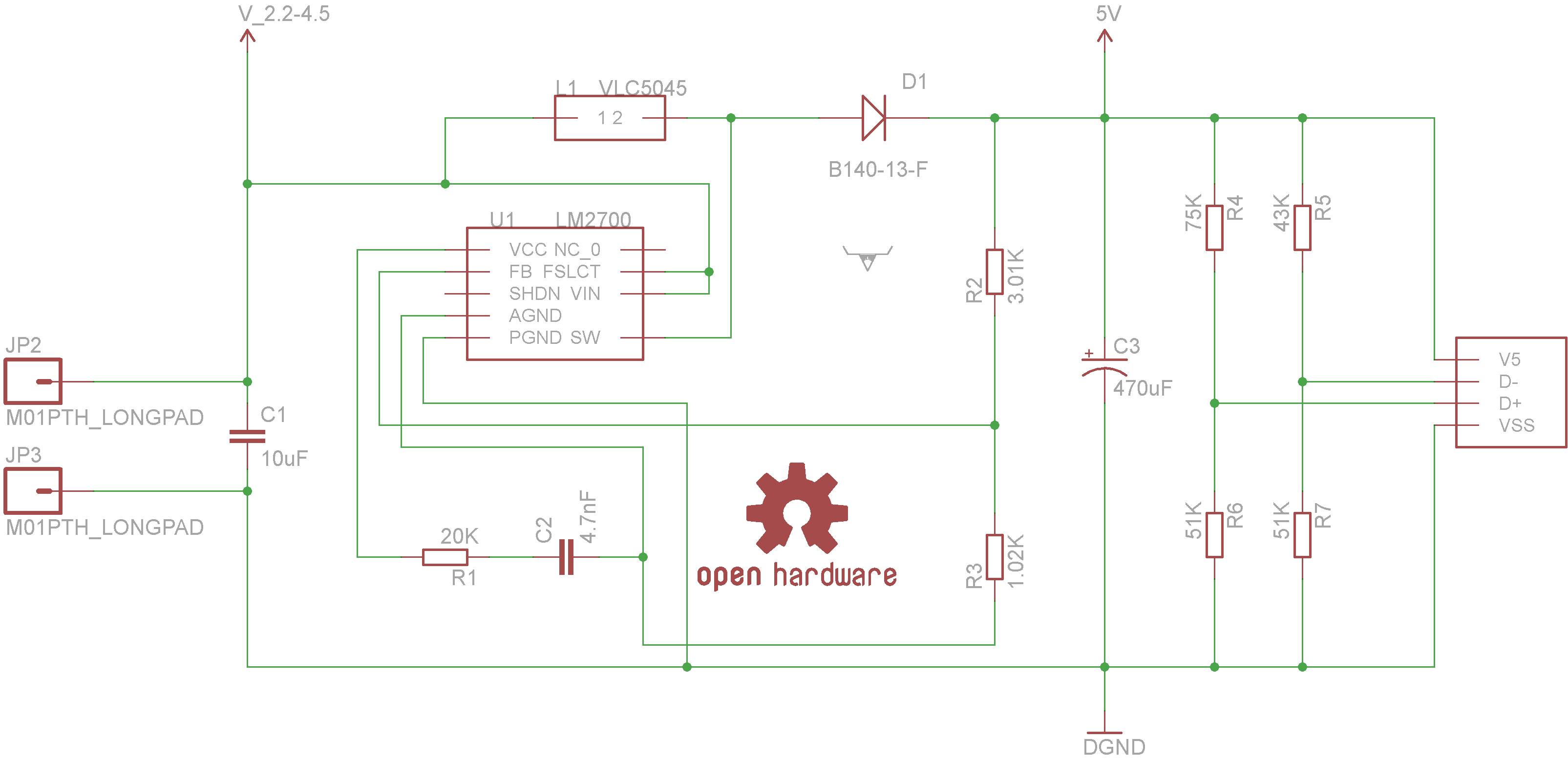
Powered by the LM2700 IC, this charger is capable of recharging devices such as MP3 players, cameras, cell phones, and any other gadgets that can be connected to a USB port at an accelerated rate. The circuit utilizes the LM2700...
This discussion assists in selecting the most appropriate microprocessor supervisor integrated circuit (IC) for specific applications and provides solutions for various common supervisory issues encountered with microprocessors. Microprocessor supervisor ICs are critical components in ensuring the reliable operation of microprocessor-based...
Although not a new device, the LM317 is still a high-performance regulator. Its output voltage is essentially immune to fluctuations in load and supply voltage. The LM317 is a versatile adjustable linear voltage regulator widely used in various electronic applications....
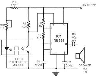
This smoke detector utilizes a 555 timer circuit along with common electronic components. The photo interrupter module serves as the smoke detection element, while the 555 timer is configured in astable mode to function as an audio frequency oscillator,...
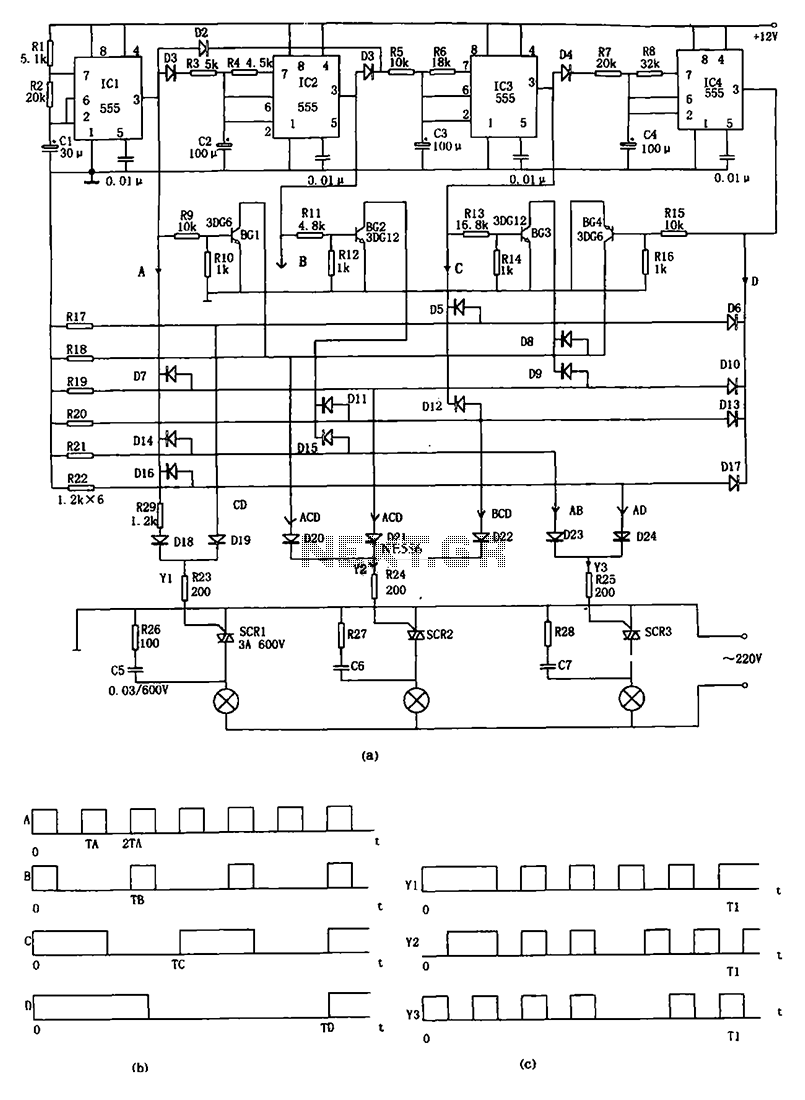
The decorative lamp control circuit is illustrated in the figure. The controller comprises a pulse generator, a frequency divider, a matrix circuit, and a thyristor control circuit. Components IC1, R1, R2, C1, and others form a multivibrator where the...
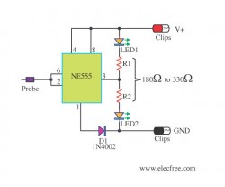
This circuit allows users to determine whether a specific point in the circuit is at a positive or negative voltage. It is an inexpensive circuit that utilizes minimal components, making it suitable for use in automobiles or motorcycles. The...