
positive negative probe with ic 555
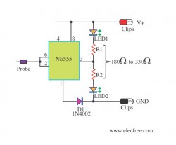
This circuit employs an integrated circuit (IC) 555 configured in a comparator mode to differentiate between positive and negative voltages. The circuit's design is straightforward, comprising the IC 555, two light-emitting diodes (LEDs) for visual indication, and a protective diode (1N4002).
The power supply for the circuit is connected across the power pins of the IC, ensuring that it operates within the specified voltage range of 5 to 15 volts. The two LEDs serve as indicators: the red LED signifies the presence of a positive voltage, while the green LED indicates a negative voltage. The operation of the LEDs is controlled by the output of the IC 555, which changes state based on the voltage level detected at its input pin.
When a positive voltage is applied to pin 3 of the IC, the output goes high, activating the red LED and illuminating it. Simultaneously, the green LED is turned off. This visual feedback allows the user to easily ascertain the polarity of the voltage at the test point. On the other hand, when a negative voltage is applied, the output of the IC changes state, turning off the red LED and illuminating the green LED.
The inclusion of the 1N4002 diode is crucial for protecting the circuit from potential damage due to incorrect polarity connections. This diode ensures that the current flows in the correct direction, safeguarding sensitive components within the circuit.
Overall, this circuit is a practical solution for quickly identifying voltage polarity in automotive or motorcycle applications, providing an efficient and low-cost method for users to check voltage levels safely. The simplicity of the design makes it accessible for both novice and experienced electronics enthusiasts.With this circuit you can can check that which dot of the circuit is Positive Volt or Negative Volt which. This cheap circuit uses the a little component is will appropriate apply with an automobile or motorcycle.
This circuit works during Voltage between 5-15V. When build volt supply of circuit LED 2 pcs. of stick bright but enough check meet Pos itive Volt make at pin 3 of IC 555 liberate Negative volt come out cause Red LED stick bright next but Green LED switch off down replace. But when check meet Negative Volt make Red LED switch off but Green LED stick bright replace yes. The Diode 1N4002 be formed protect turning pole electricity over. The detail is other, see in the circuit please sir. 🔗 External reference
Related Circuits

This logic probe features four channels and employs two quad comparator integrated circuits to drive four bicolor LEDs. The SI and SIB pins are used to set the comparator trip levels for TTL and CMOS logic families. Resistors R6...

A voltage-controlled oscillator using the NE555. This circuit is commonly referred to as a voltage-to-frequency converter because the output frequency is altered by varying the input voltage. As previously noted, pin 5 serves as the voltage control terminal, which...
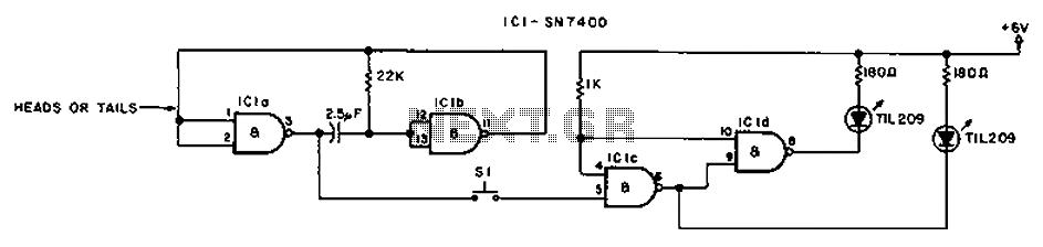
The circuit involves a switch (S1) that facilitates the release of current when it reaches the shut-off mechanism. The circuit operates by utilizing a switch (S1) that plays a crucial role in controlling the flow of current within the system....
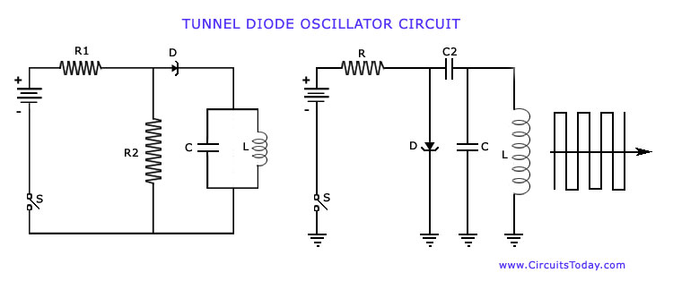
The operation of Negative Resistance Oscillators, including types such as Dynatron and Tunnel Diode Oscillator, along with their characteristics and circuit diagrams, is explained. Negative resistance oscillators are electronic circuits that exploit the phenomenon of negative resistance to generate oscillations....
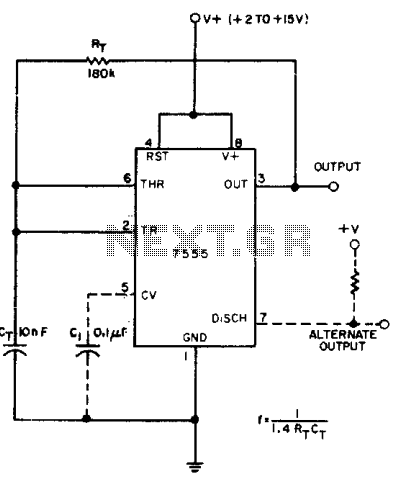
A CMOS timer generates true square waves because, unlike the bipolar 555, its output swings from rail to rail. The component values shown give a frequency of about 400 Hz. The CMOS timer circuit operates by utilizing complementary metal-oxide-semiconductor technology...
This circuit detects metal and also magnets. When a magnet is brought close to the 10mH choke, the output frequency changes. The circuit operates on the principle of inductance variation in response to the presence of a magnetic field. The...