
12V Glow Plug Converter
The described circuit is a compact and efficient solution for powering glow plugs in small internal combustion engines used in model building. The use of a DC/DC converter allows for the elimination of the inefficient 2-V battery and diode setup, thus enhancing overall energy efficiency. The MAX 1627 IC plays a pivotal role in the circuit, providing the necessary voltage regulation through its step-down operation. The selection of a suitable FET, such as the 2SJ349, is critical as it directly impacts the performance and reliability of the converter. The fast Schottky diode ensures rapid response times and minimal voltage drop during operation, which is essential for maintaining the efficiency of the power delivery to the glow plug.
Careful consideration of component specifications, particularly the resistances of the inductor and capacitors, will further optimize performance and thermal management. The design allows for flexibility in output voltage adjustments through the resistor network, accommodating various glow plug requirements. The emphasis on proper assembly techniques, such as the placement of capacitors and the use of appropriate gauge wiring, is vital to handle the high currents involved without risking overheating or voltage drops. This circuit design exemplifies a practical approach to powering glow plugs effectively, ensuring reliable engine start-up in model applications.Most small internal-combustion engines commonly used in the model-building world use glow plugs for starting. Unfortunately, glow plugs have an operating voltage of 1. 5 V, while fuel pumps, starter motors, chargers and the like generally run on 12 V. This means that a separate battery is always needed to power the glow plug. The standard solutionis to use an additional 2-V lead storage battery, with a power diode in series to reduce the voltage by approximately 0. 5 V. However, this has the annoying consequence that more than 30 percent of the energy is dissipated in the diode.
Naturally, this is far from being efficient. The converter presented here allows glow plugs to be powered from the 12-V storage battery that is usually used for fuelling, charging, starting and so on. A car battery can also be used as a power source. Furthermore, this circuit is considerably more efficient than the approach of using a 2-V battery with a series power diode.
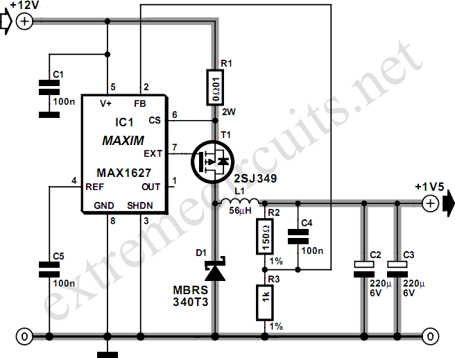
The heart of the DC/DC converter is IC1, a MAX 1627. The converter works according to the well-known step-down principle, using a coil and an electrolytic capacitor. Here the switching stage is not integrated into the IC, so we are free to select a FET according to the desired current level.
In this case, we have selected a 2SJ349 (T1), but any other type of logic-level FET with a low value of RDSon would also be satisfactory. Of course, the FET must be able to handle the required high currents. Diode D1 is a fast Schottky diode, which must be rated to handle the charging currents for C2 and C3.
This diode must also be a fairly hefty type. The internal resistances of coil L1 and capacitors C2 and C3 must be as low as possible. This ensures efficient conversion and prevents the components from becoming too warm. The resistor network R2/R3 causes 87 percent of the output voltage to be applied to the FB pin of IC1. This means that an output voltage of 1. 5 V will cause a voltage of approximately 1. 3 V to be present at the FB pin. The IC always tries to drive the switching stage such that it sees` a voltage of 1. 3 V on the FB input. If desired, a different output voltage can be provided by modifying the values of R2 and R3. When assembling the circuit, ensure that C5 and C1 are placed as close as possible to IC1, and use sufficiently heavy wiring between the 12-V input and the 1-5-V output, since large currents flow in this part of the circuit.
A glow plug can easily draw around 5 A, and the charging current flowing through the coil and into C2 and C3 is a lot higher than this! 🔗 External reference
Related Circuits
If you are looking for ICs for a DC to DC converter application, the LM1577/LM2577 ICs are highly recommended as they provide all the necessary power and control functions for step-up conversion. The LM1577 and LM2577 are versatile integrated circuits...
The circuit illustrated in the schematic diagram below is an isolated DC-to-DC step-up converter. The term "isolated" indicates that there is no electrical connection between the input and output sections of the circuit. The isolated DC-to-DC step-up converter operates by...
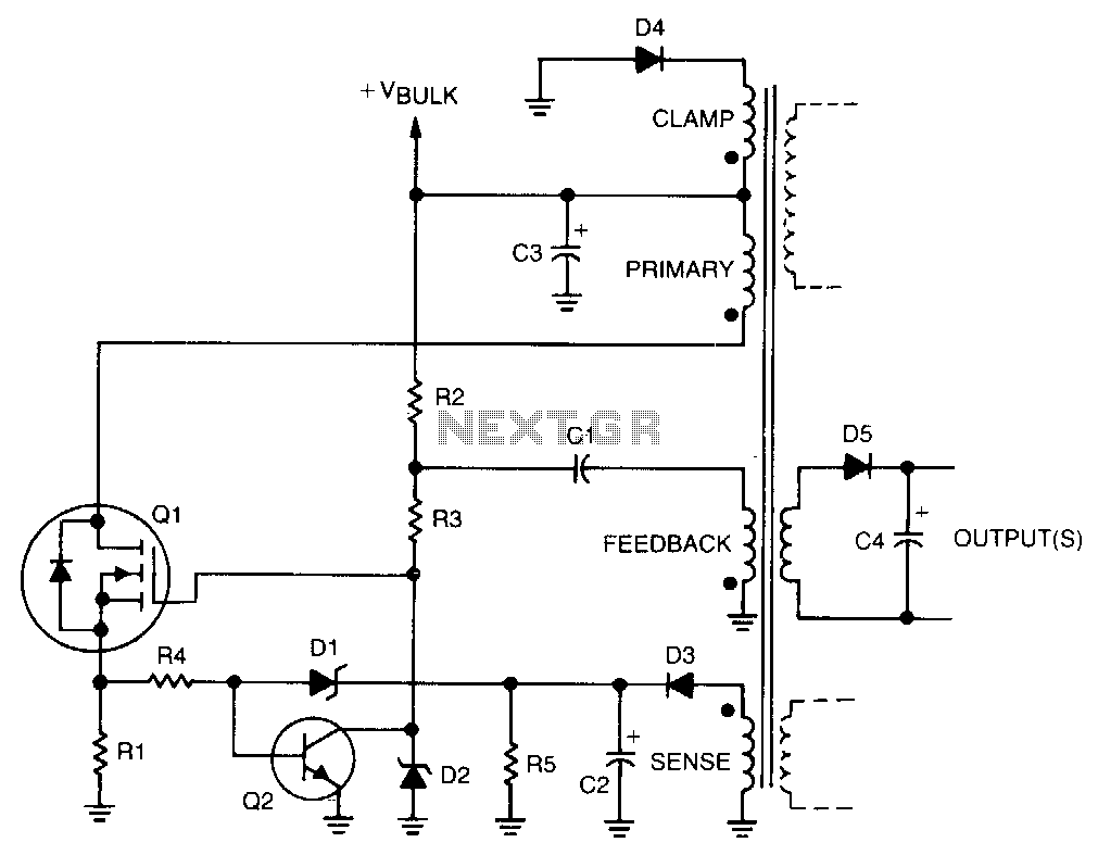
Regulation is achieved by using the rectified output from the sense winding, which is applied as a bias to the base of transistor Q2 through Zener diode D1. The collector of Q2 then disconnects the drive from the gate...
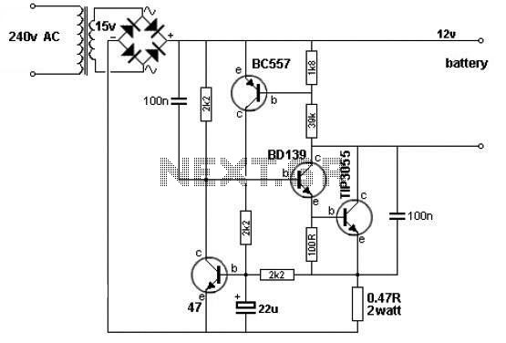
A simple 12V battery charger circuit can be designed using a TIP3055 power transistor to limit the current to the battery. The circuit turns off when the battery voltage reaches approximately 14V or if the current exceeds 2A. This...
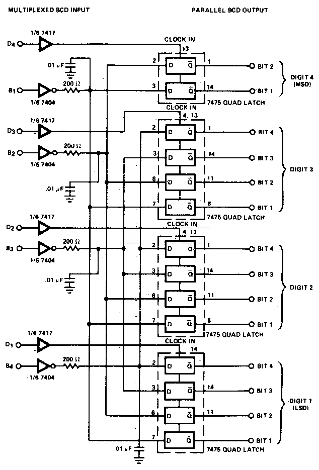
The converter is composed of four quad bistable latches that are activated in the correct sequence by the digit strobe output from the LD110. The complemented outputs (Q) of the quad latch set represent the state of the bit...
There are many individuals interested in listening to frequencies within the VHF range of 108 to 132 MHz. This VHF AM converter is designed to convert signals from a frequency band of 106 to 150 MHz, allowing users to...