
Schematic Diagram 12v battery charger circuit
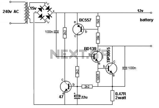
The described 12V battery charger circuit functions through a combination of transistor switching and voltage feedback mechanisms to ensure safe charging of the battery. The TIP3055 serves as the main power transistor, capable of handling significant current loads up to 15A, making it suitable for charging applications. The circuit's design incorporates a current limiting feature that prevents damage to the battery by ceasing operation when either the voltage exceeds 14V or the current surpasses 2A.
The BC557 and BC547 transistors are configured as a feedback control mechanism. The BC557 is a PNP transistor that activates when the voltage across the voltage divider reaches a threshold, turning on to signal the TIP3055 to stop charging. The voltage divider, formed by the 1.8kΩ and 39kΩ resistors, plays a critical role in setting this threshold. As the battery charges and its voltage rises, the voltage at the divider increases, eventually reaching 0.65V. This triggers the BC557, which in turn influences the TIP3055 to shut off, thus protecting the battery from overcharging.
In the initial state, the circuit is fully operational, with the BD139 transistor driving the TIP3055 to allow current to flow into the battery. The BD139 is an NPN transistor that ensures that the TIP3055 remains on until the feedback from the BC557 indicates that the battery is sufficiently charged. The overall simplicity of the circuit, with its reliance on just a few transistors and resistors, makes it an effective solution for charging 12V batteries in various applications, including automotive and renewable energy systems.
In summary, this battery charger circuit exemplifies a straightforward yet effective design that utilizes transistor switching to manage battery charging safely and efficiently. The careful selection of components and their arrangement allows for reliable operation while minimizing the risk of overcharging, thus extending the lifespan of the battery being charged.A very simple 12v battery charger circuit can be designed using a TIP3055 power transistor to limit the current to the battery by turning off when the battery voltage reaches approx 14v or if the current rises above 2 amp. This battery charger electronic circuit is very simple and require few external electronic parts. Signal to turn off the TIP3 055 transistor comes from two other transistors, the BC557 and BC 547. Firstly, the circuit turns on fully via the BD139 and TIP3055. The BC557 and BC 547 do not come into operation at the moment. As the battery voltage rises, the voltage divider made up of the 1k8 and 39k creates a 0. 65v between base and emitter of the BC557 and it starts to turn on at approx 14v. 🔗 External reference
Related Circuits
The audio amplifier illustrated in this circuit diagram is a straightforward and efficient audio amplifier circuit based on the TDA1308 integrated class-AB stereo headphone amplifier. This device is manufactured using a 1 mm Complementary Metal Oxide Semiconductor (CMOS) process...
A simple digital circuit is presented that can be used to precisely control the AC power supply. This circuit does not include a digital-to-analog conversion component. In its application, effective control is established through a computer system that sends...
A small electronic switch connects a battery to equipment for a specific duration when a push-button is momentarily pressed. The circuit also considers ambient light levels; when it is dark, the display cannot be read, so it is logical...
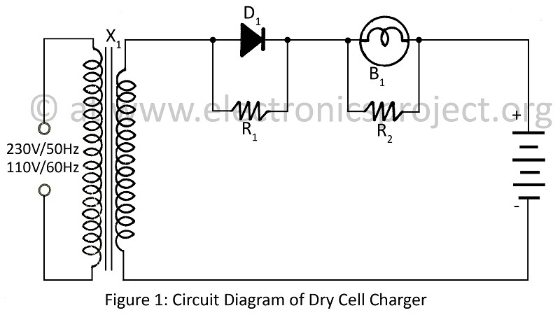
A dry cell charger designed to recharge dry cells 6 to 8 times using a minimal number of components, based on the principle of Periodic Current Reversal (PCR). The circuit diagram is applicable to various projects. The dry cell charger...
The figure illustrates the voltage-current (V-I) curve for a typical solar panel (Sharp ND-224U1F) and its output power under varying lighting conditions. The solar panel operates as a constant current source at high currents and as a voltage source...

Figure 1-122 is a dedicated high-fidelity surround sound processing integrated circuit (IC) TDA3810 circuit that manages surround sound. The stereo signal is processed through input coupling capacitors C1 and C2. The internal buffer amplifier handles the left and right...