
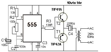
12V Lead Acid Battery Desulphator
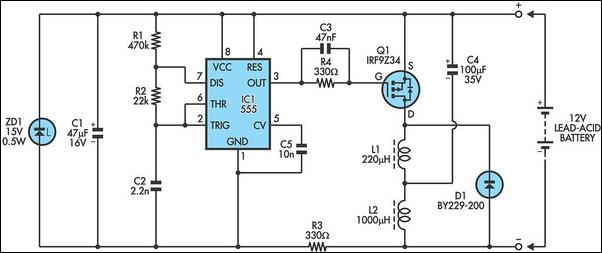
The circuit operates based on the principle of generating high-voltage pulses to mitigate lead sulfate buildup on the battery plates. The astable multivibrator configuration of the 555 timer continuously generates a square wave output, with the frequency set by the chosen resistor and capacitor values. This output drives the gate of the MOSFET Q1, enabling it to switch on and off rapidly, thus controlling the charging of the inductors L1 and L2.
When Q1 is activated, current flows through the inductors, storing energy in the magnetic field. Once Q1 is turned off, the collapsing magnetic field induces a high-voltage pulse across the inductors. This pulse is directed to the battery through the fast-recovery diode D1, ensuring that the current flows in the correct direction while protecting the circuit from back EMF. The capacitor (100 µF) serves to smooth the output pulse, providing a more stable voltage to the battery.
The inclusion of the zener diode (ZD1) is crucial for protecting the 555 timer from voltage spikes generated during the operation of the circuit. The 47 µF capacitor works in conjunction with the zener diode to filter any high-frequency noise that may affect the stability of the 555 timer operation. The 330-ohm resistor (R3) limits the current flowing into the zener diode, ensuring that it operates within its safe limits.
This circuit provides a potentially innovative approach to addressing sulfation in lead-acid batteries, although the effectiveness of reversing sulfation remains a subject of debate. Proper implementation and safety precautions should be taken into account when working with high-voltage circuits, especially in applications involving lead-acid batteries.Lead acid batteries often fail prematurely due to over-charging, under-charging, deep discharging and low electrolyte level. All of these can lead to sulphation of the plates which leads to high internal resistance and eventual failure.
Normally, this process is regarded as irreversible but this circuit is claimed to reverse the process by applyin g high voltage pulses to break down the lead sulphate compounds. The circuit is essentially a high-voltage pulse generator which is powered directly from the battery in question. If the battery is badly sulphated, it will be necessary to connect it to a low power charger as well, say 2A.
We have strong doubts about whether battery sulphation can be effectively reversed but we are publishing this circuit because the subject is of particular interest. This circuit has been submitted to us from a number of sources so we do not know who is the original designer.
More information can be found at. The 555 timer is connected as an astable oscillator with its output frequency set by R1, R2 and C2. Its output pulses drive the gate of Mosfet Q1 which turns on to charge inductors L1 and L2. At the end of each pulse, Q1 turns off and the inductors develop a high-voltage high-current pulse which is applied across the battery via fast recovery diode D1 and the 100 µF capacitor. The 555 is protected from the high voltage pulses via its isolated supply, by virtue of the 15V zener diode ZD1, the 47 µF capacitor and the 330Oresistor R3.
🔗 External reference
Related Circuits
After experiencing failures with four Apple iPad chargers and not wishing to incur further expenses by purchasing replacements from Apple, a decision was made to create 12V powered chargers. This would utilize the surplus photovoltaic (PV) power available during...
Zilog's Z8 Encore XP F1680 Series features a highly optimized set of capabilities specifically designed for stepper motor microstepping control. Key features of the Z8 Encore! XP F1680 include: an 11 MHz internal oscillator, two analog comparators, a 10-bit...
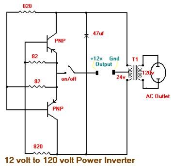
This is the schematic diagram of a 15W inverter circuit. The circuit is based on a PNP power transistor such as the TIP32 and other similar transistors. This inverter produces a square wave output, which may cause some noticeable...
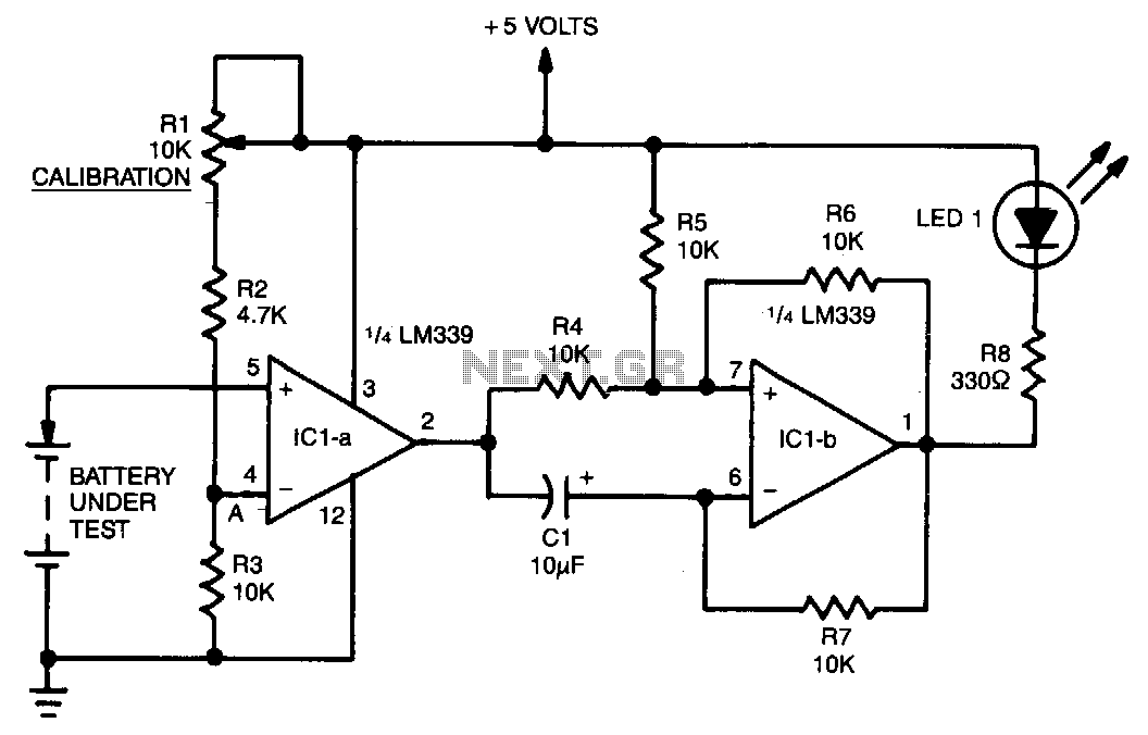
A voltage divider consisting of R1, R2, and R3 is utilized to establish the input reference voltage below which the batteries should be replaced. The reference voltage at point A is adjustable via R1. As illustrated in the diagram,...
12V power inverter circuit utilizing a 555 timer for an electronic project. The 12V power inverter circuit is designed to convert a DC voltage of 12 volts into an AC voltage suitable for powering small electronic devices. The core component...
This high-performance charger efficiently charges gelled lead-acid batteries and automatically shuts off upon reaching a full charge. Initially, the charging current is maintained at 2 A; however, as the battery voltage increases, the current gradually decreases. Once the current...