
12V power inverter using 555 timer circuit
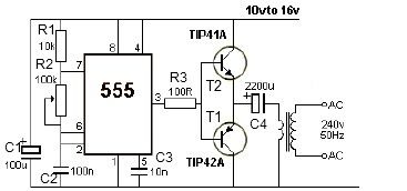
The 12V power inverter circuit is designed to convert a DC voltage of 12 volts into an AC voltage suitable for powering small electronic devices. The core component of this inverter is the 555 timer IC, which is configured in astable mode to generate a square wave signal. This square wave signal is crucial for driving the output stage of the inverter, which typically consists of a transformer and a pair of transistors.
In this configuration, the 555 timer generates a frequency that is determined by the resistors and capacitors connected to it. The output of the 555 timer is fed into the base of the transistors, which act as switches. When the timer output goes high, it turns on one transistor, allowing current to flow through the primary winding of the transformer in one direction. When the output goes low, the other transistor is turned on, reversing the current flow through the transformer. This alternating current (AC) in the transformer's secondary winding produces the desired output voltage.
The transformer is selected based on the required output voltage and power rating. A step-up transformer is commonly used to increase the voltage from the 12V input to a higher AC voltage, typically around 120V or 230V, depending on the application's requirements.
Additional components, such as diodes and capacitors, may be included in the circuit for protection and filtering purposes, ensuring stable operation and reducing voltage spikes. A heat sink may also be added to the transistors to dissipate heat generated during operation, enhancing reliability.
This inverter circuit is suitable for various applications, including powering small household appliances, LED lights, and other low-power devices, making it a versatile project for electronics enthusiasts and engineers.12V power inverter circuit using 555 timer circuit electronic project. 🔗 External reference
Related Circuits
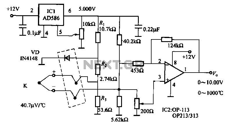
The circuit includes a K-type thermocouple cold junction compensation circuit, a precision 5.000V reference voltage source, and an OP113 operational amplifier. It is capable of measuring temperatures ranging from 0°C to 100°C with a resolution of 0.02°C. The OP113...
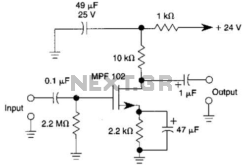
This JFET preamplifier has a gain of approximately 20 dB and a bandwidth exceeding 100 kHz. It is useful as a low-level audio amplifier for high-impedance sources. The described JFET (Junction Field Effect Transistor) preamplifier is designed to amplify low-level...
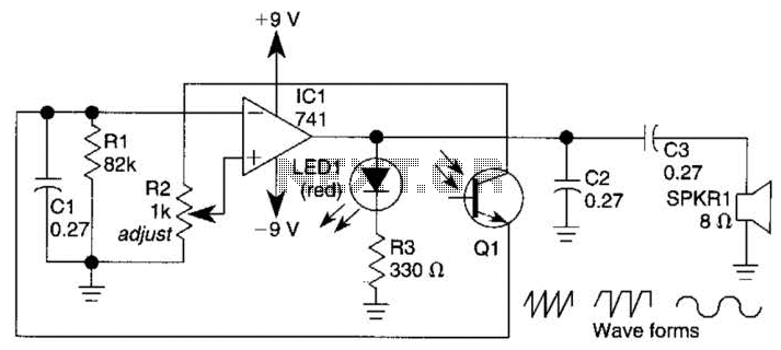
A 555 timer operating in astable mode generates driving pulses, while two 4518 dual BCD (binary coded decimal) counters provide square waves. A TL081 operational amplifier functions as an output buffer-amplifier. Potentiometers R1 and R2 are utilized to control...
A voltage supply ranging from 6 V to 15 V is required when using a single LED per module. An increase in the number of LEDs necessitates a corresponding increase in the voltage supply, with additional LEDs connected in...
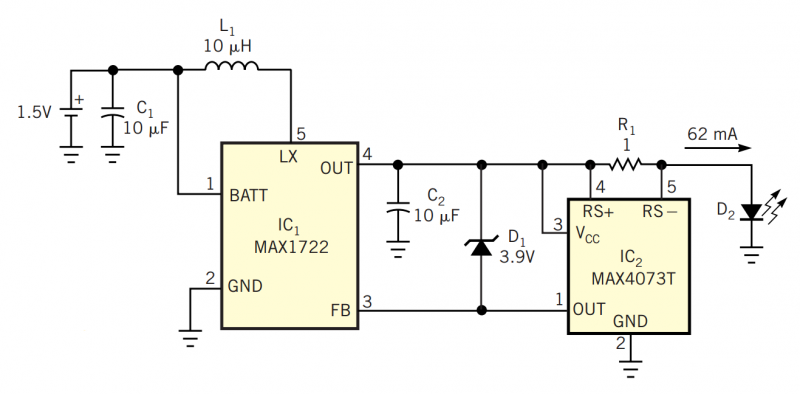
Although white LEDs are common in a variety of lighting applications, their 3 to 4V forward-voltage drop makes low-voltage applications challenging. Charge pumps and other ICs are available for driving white LEDs, but they generally don't work with the...
The Electronics Schematic Diagram MJR7-Mk3 Mosfet MJR6 page includes distortion extracted using the nulling method with a speaker load and a music signal to demonstrate that these designs have no audible distortion in normal use. The MJR7 has even...
Warning: include(partials/cookie-banner.php): Failed to open stream: Permission denied in /var/www/html/nextgr/view-circuit.php on line 713
Warning: include(): Failed opening 'partials/cookie-banner.php' for inclusion (include_path='.:/usr/share/php') in /var/www/html/nextgr/view-circuit.php on line 713