
12v led lamp circuit
The 12V LED lamp circuit is designed to provide efficient illumination through the use of super bright white 5mm LEDs. The circuit's simplicity is one of its key features, making it accessible for hobbyists and engineers alike. The configuration includes five resistors, which are used to limit current and ensure that the LEDs operate within their specified voltage and current ratings, thereby enhancing their lifespan and performance.
The circuit operates on a 12-volt power supply, which can be sourced from various types of batteries, including standard lead-acid batteries, which are commonly found in automotive applications. The ability to function with a car battery adds to the versatility of this circuit, allowing it to be used in a variety of settings, such as emergency lighting during power outages or as a portable light source.
In practical testing, the circuit was powered by a 4.5AH lead-acid battery, demonstrating its capability to serve as a reliable emergency light. The performance was notable, with the circuit providing illumination for several days under continuous use of 2 to 3 hours each day. After this duration, the battery voltage was recorded at 9 volts, indicating that the circuit effectively utilized the battery's capacity while still maintaining operational efficiency.
This LED lamp circuit is an excellent example of how simple electronic components can be combined to create a functional and cost-effective lighting solution. Its straightforward design allows for easy assembly and troubleshooting, making it an ideal project for those looking to gain practical experience in electronics.A very useful project of a 12V LED Lamp circuit. This led circuit is very simple consist of 5 resistors and 15 super bright white 5mm LEDs which are easily available now a days on very cheap prices. You can use any type of 12 volt battery with this circuit. You can also use this lamp circuit with car battery. The circuit is tested with 4. 5AH lead acid battery and it served for several days as emergency light circuit and gave a very long back up with only 4. 5AH lead acid battery. After countinous operation of 2 to 3 hours daily for several days the battery showed 9 volts on digital multimeter meter.
🔗 External reference
Related Circuits
The device is designed as a panel meter suitable for use in DC power supplies or any application that requires accurate voltage indication. It utilizes the CL7107 integrated circuit (IC) from INTERSIL, which is housed in a 40-pin package...
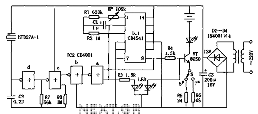
The CD4001/CD4541 nickel-cadmium battery automatic charger circuit is illustrated in the figure. This circuit is designed for charging up to seven rechargeable nickel-cadmium batteries. It features automatic charging with constant current characteristics. Once powered, the circuit activates an internal...
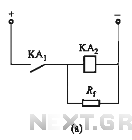
The circuit depicted in Figure 6-24 includes a relay coil with both ends connected in parallel to either a resistor Rf or an auxiliary diode VD. This configuration is equivalent to providing power after a short circuit, which increases...
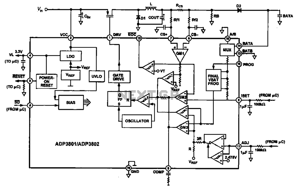
Charging circuit diagram for personal work based on the operating principle of ADP3801/3802 charging circuit. The ADP3801/3802 is a highly integrated battery charger controller designed for Li-ion and Li-polymer batteries. The charging circuit typically consists of several key components including...
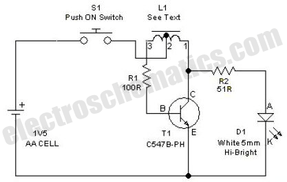
This simple LED driver circuit allows the operation of up to seven LEDs using a single NiMH (Nickel Metal Hydride) AA cell. The circuit generates voltage pulses. The LED driver circuit is designed to efficiently power multiple LEDs while maintaining...
A zero-crossing detector converts an input sine wave (Vin) into a square wave, which, when high, charges an op-amp integrator. A reference-input square wave subsequently discharges the integrator. The output voltage of the integrator at the end of this...
Warning: include(partials/cookie-banner.php): Failed to open stream: Permission denied in /var/www/html/nextgr/view-circuit.php on line 713
Warning: include(): Failed opening 'partials/cookie-banner.php' for inclusion (include_path='.:/usr/share/php') in /var/www/html/nextgr/view-circuit.php on line 713