
12v sensor light

The circuit modification process involves several key considerations. First, the power supply must be adjusted to ensure compatibility with 12 volts, which includes replacing components such as the relay. The design must account for the LDR's functionality, ensuring it remains effective in daylight conditions. The removal of the bridge rectifier, while simplifying the circuit, requires careful consideration of the potential for reversed polarity connections. Retaining or replacing R1 with an appropriate fusible resistor ensures protection against overcurrent scenarios.
Additionally, the mains sense input requires careful handling. It is crucial to determine the optimal connection point in relation to the circuit's operation. The need for an AC signal for reliable function may necessitate additional components or circuitry to simulate the required conditions. This could involve integrating a small transformer or capacitor to create the necessary AC environment for the sensor to operate effectively.
In summary, while the adaptation of a 240-volt sensor light to 12 volts is feasible, it demands meticulous attention to component selection, circuit design, and testing to ensure reliable operation in a security application. The process underscores the importance of understanding the underlying principles of the circuit and the specific requirements for successful modification.I wanted to add a security/sensor light near the main doorway that would run of 12 volts. You can buy 12 volt PIR sensors, but these are very expensive at over $50 each and designed for security systems. However you can pick up a 240v sensor light for less than $20 from any hardw are store, so I wondered if one of these could be converted to 12v operation. I already had this sensor lamp, so it was the guinea pig. Once I opened the sensor case ( after I of course disconnected the lamp from the mains power ), and accidentally broke off the small adjustment knobs, I found the sensor consisted of two circuit boards. Shown in the picture below (remember you can click on most pictures to see a larger image ), the left circuit board is the sensor, and the right circuit is power and relay driver.
There is also a LDR ( Light Dependent Resistor ) there, this is used to stop the lamp turning on during the day. When you test your sensor light, remember to cover this with black tape to block out the light. Another thing to remember when you want to test you sensor, is the PIR will only work with the frenzel lens in place.
This is a generic circuit for these sensor lamps, the component values may vary from model to model. R1 is a fusible resistor, so it acts as a fuse as well as a dropping resistor. C1 and R2 are the main voltage dropping components. Diodes D1 to D4 make a bridge rectifier, fed into C2, our main filtering cap, and then a 5 volt regulator, to supply 5 volts to the sensor circuit. In some models I`ve see zener diodes used in the bridge rectifier, or across the output, to keep the voltage below 30 volts.
This protects the 5v regulator from excessive input voltage. Transistor Q1 receives it drive from the sensor circuit, and switches a 24v relay, turning on the lamp when the unit detects motion. Resistor R3 is the mains power sense input to the sensor circuit, and this can be a little tricky. Basically when the mains power is switched off and on quickly, the circuit switches the lamp on, and keeps it on, until the power is turned off for 10 or more seconds.
The idea is you can flick you light switch to make the sensor lights stay on, but as everyone knows, it also means the sensor lights come on and stay on after a dip in the mains power, which is a real pain in the bum. Most of the circuit runs at 5 volts, so it should be a straight forward process to convert these lamps to 12v operation, but there are a few little problems we need to sort out.
You can see I`ve removed the voltage drop components and the bridge rectifier. You could leave the bridge rectifier there as a safety measure in case you swap the +ve and -ve connectors, but remember this introduces a voltage drop of about 1. 2 volts. I`ve also replaced R1 with a 1R fusible resistor. Or I could have just used a fuse, the circuit board above is a good model and has a fuse already on the circuit board.
My power supply will be 12v, so I need to replace the 24v relay with a 12v relay. However, if you wanted to run this circuit from a 24v source you could leave the 24v replay in place. R3, the little bugger! A few years ago I converted one of these sensor lights to 12v operation as part of a burglar alarm for my car, and I remember I needed to connect this mains sense input to +12v to make the circuit work properly.
So this time I went out and bought a Arlec sensor light from Dick Smith for $19, and tried the same connection for the mains sense input. Didn`t work, in fact I could not get the thing to work reliable at all. I found this sense wire on this model needs to see AC to work properly, if I connected it to ground or power it would not work, if I let the input float free, it would pick up enough AC hum in the air to work, most of the time!
I even tried a length of wire on this input to act as a aerial, still no reliable operation, so I gav 🔗 External reference
Related Circuits
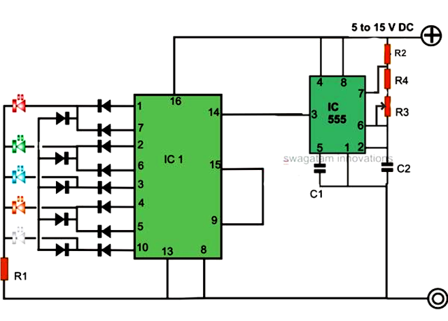
An LED light chaser circuit is an electronic configuration designed to illuminate a group of LEDs in a predetermined sequence. A commonly used integrated circuit (IC) for creating this type of LED sequencer circuit is the 4017. This IC...
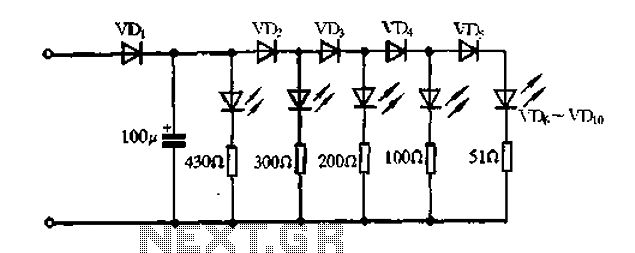
A passive light-emitting diode output level indication circuit. This circuit utilizes a light-emitting diode (LED) to provide a visual indication of the output level from a given source. The design is characterized by its passive nature, meaning it does not...
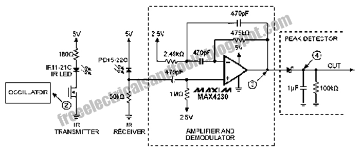
The following circuit illustrates an Infrared Proximity Sensor Circuit Diagram. This circuit is based on the MAX4230 integrated circuit. Features include a 10 kHz oscillator. The Infrared Proximity Sensor Circuit utilizing the MAX4230 integrated circuit is designed to detect the...
A simple tool to check the degree of radiation from an electric or electronic instrument. The LEDs in the circuit will provide a running light pattern when the circuit detects electromagnetic radiation from the device. It can identify radiation...
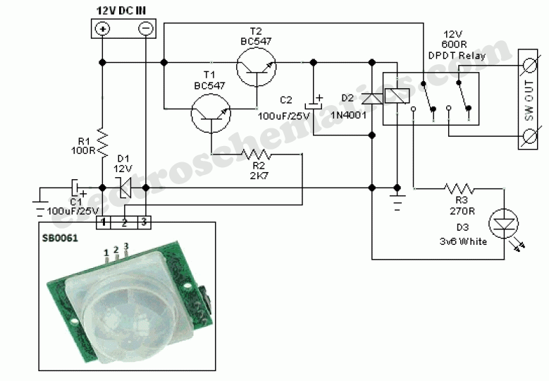
This circuit represents a general-purpose white LED security light equipped with a Passive Infrared (PIR) motion sensing mechanism. The core component of the circuit is the PIR sensor module SB0061, which is a pyroelectric sensor designed for human body...
This circuit is a simple manual analog light control desk that outputs standard 0-10V control signals suitable for controlling professional light dimmers and other lighting equipment. The controller's output is a steady DC voltage that varies between 0 and...