
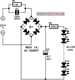
A passive light emitting diode output level indication circuit
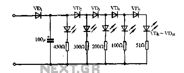
This circuit utilizes a light-emitting diode (LED) to provide a visual indication of the output level from a given source. The design is characterized by its passive nature, meaning it does not require an active power source to operate the LED. Instead, the circuit relies on the voltage generated by the output signal to illuminate the LED.
The core components of this circuit include the LED, a current-limiting resistor, and the output source. When the output voltage exceeds a certain threshold, it forward-biases the LED, allowing current to flow through it. The current-limiting resistor is essential to prevent excessive current from damaging the LED, ensuring that it operates within its specified parameters.
In practical applications, this circuit can be implemented in various devices to provide a simple and effective visual representation of output levels, such as in audio equipment to indicate signal presence or in power supply circuits to show operational status. The passive nature of this circuit makes it suitable for low-power applications where minimal power consumption is desired.
To enhance the functionality of the circuit, additional components such as diodes or transistors may be incorporated to improve response times or to create multi-level indication systems, where different LED colors or multiple LEDs indicate varying levels of output. Overall, this passive LED output level indication circuit serves as an efficient solution for visual feedback in electronic systems.A passive light emitting diode output level indication circuit
Related Circuits

A simple 16-volt switching power supply circuit can be constructed using the provided diagram, which is based on the MAX668 constant-frequency, pulse-width modulating (PWM), current-mode DC-DC controller. This integrated circuit is designed for a wide range of DC-DC conversion...
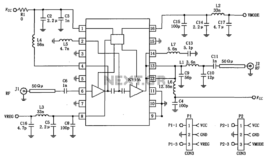
The circuit depicted in the figure is a 380MHz RF2175 linear amplifier application circuit. The radio frequency (RF) signal is input from pin 6 and is processed through a preamplifier, followed by a final power amplifier stage. The output...
This meter circuit utilizes a single integrated circuit (IC) and a minimal number of external components. It displays audio levels using ten light-emitting diodes (LEDs). The input voltage can range from 12V to 20V, with a recommended voltage of...
White LEDs have a rated current at a voltage drop of about 3.3 to 3.4 V. It is ideal to be powered from the battery voltage which is slightly larger. Then there is the best energy used. In this...
Hello everyone. This is my first post in quite some time. I obviously do not have an old enough catalog for reference. In the data section, there were references to... The input data indicates a lack of sufficient information regarding...
Utilize this FM antenna amplifier in locations where the reception of FM stations is poor. This circuit is specifically designed for this purpose. The FM antenna amplifier circuit is engineered to enhance signal strength for FM radio stations, particularly in...
Warning: include(partials/cookie-banner.php): Failed to open stream: Permission denied in /var/www/html/nextgr/view-circuit.php on line 713
Warning: include(): Failed opening 'partials/cookie-banner.php' for inclusion (include_path='.:/usr/share/php') in /var/www/html/nextgr/view-circuit.php on line 713