
12v stroboscope 250 400v dc circuit

The stroboscope circuit operates by first stepping up the input voltage to the required levels for the tube's operation. The transistors Q1 and Q2 are configured in a push-pull arrangement, allowing them to alternately drive the transformer T1. The transformer is designed to increase the voltage from a lower input level to approximately 230V AC, suitable for the subsequent rectification process.
The diode bridge U1 is crucial in converting the AC output from the transformer into DC voltage. It is essential that U1 is rated for at least 400V to ensure safe operation under maximum load conditions. The rectified voltage is then filtered and smoothed by capacitor C1, which stores the energy required for the stroboscope tube to function effectively.
The components used in the construction of this stroboscope, particularly the beam tube and reflector, were repurposed from an old camera flash unit, showcasing an efficient use of available resources. The triggering circuit employs a triac, which is responsible for initiating the discharge of the stored energy in C1 to produce the necessary flash. The selection of a triac capable of handling at least 1A and 400V ensures reliable operation and longevity of the circuit.
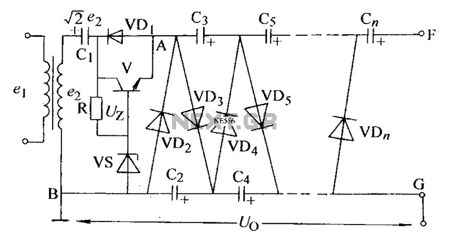
This design exemplifies a practical application of electronic components in creating a high-voltage stroboscopic light source, leveraging both salvaged parts and readily available components to achieve the desired functionality. Proper attention to component ratings and circuit design ensures safety and effectiveness in operation.The stoboscope tube needs about 250-400V DC to operate. This aerial voltage is generated application simple voltage footfall up ambit congenital from transistors Q1, Q2 and agent T1. This ambit gives out about 230V AC voltage which is again rectified with afterlight arch U1 (must accept at atomic 400V voltage rating) and stored to the capital capac
itor C1. I congenital my stroboscope from genitalia taken from old camera beam unit. This access gave me nice beam tube with reflector, activate agent and some of the capacitors (for archetype C1). Other genitalia were the one luying around. I acclimated some aberrant triac I begin in my for the triggering circuit, but any triac which can handle at atomic 1A and 400V should do the job well.
🔗 External reference
Related Circuits

A front wheel with a built-in dynamo was purchased, providing a sine wave output of 30 Vpp at no load. Based on this, a simple power supply was designed using BD911 transistors, which are somewhat oversized for the application,...

Integrated circuit gates IC1-a and IC1-b form a monostable multivibrator, whose time constant is determined by capacitor C2 and resistor R3. When the transmitter is dekeyed and then almost immediately rekeyed, point TX+ goes low, causing pin 1 to...

The previous tutorials on SPICE simulation in Fedora Electronic Lab have introduced various concepts. This post focuses on Part 3, assuming familiarity with gschem and completion of a course on analog electronic circuits. It is advised to review the...
The circuit is an adjustable output voltage regulator type rectifier. It allows for obtaining peak voltage at odd multiples when the output voltage is taken from the circuit feedback (FB). Additionally, the lower point of the capacitor (CB) can...
Precious metals can sometimes be buried too deep to be detected without complex devices. However, smaller pieces of precious metals located near the surface can often be found using simpler methods. Many individuals are drawn to the prospect of...

This is the design circuit diagram of an ultrasonic mosquito repeller. The circuit operates based on the theory that insects, such as mosquitoes, can be repelled by sound frequencies in the ultrasonic range (above 20 kHz). The circuit utilizes...