
Tone Burst Generator Circuit

The circuit utilizes two integrated circuit gates, IC1-a and IC1-b, configured as a monostable multivibrator. The monostable multivibrator is characterized by a single stable state and a temporary unstable state triggered by an input signal. The timing characteristics of the circuit are determined by the resistor R3 and capacitor C2, which define the duration of the output pulse.
When the transmitter is dekeyed, the signal at TX+ transitions to a low state, which pulls pin 1 of IC1-a low momentarily. This low signal serves as a trigger for the monostable, initiating the timing sequence. As C2 begins to charge through R3, the voltage across C2 rises until it reaches the threshold voltage of IC1-b, at which point the monostable output transitions, causing pin 3 to go low.
The timing period, noted to be around 700 ms in the prototype, is critical for ensuring that the output pulse is of adequate duration to be effective while remaining inaudible. This characteristic is essential in communication applications where the timing of signals can influence the clarity and integrity of the transmitted information.
In scenarios where immediate rekeying occurs, the TX+ signal returns to a high state while the monostable is still active. This condition allows for the oscillations generated by IC1-c to be integrated into the transmission signal. The enabled state of the buffer gate IC1-d facilitates the passage of the oscillation signal to the output, ensuring that any tone generated during this period is effectively transmitted. This function is particularly useful in applications where tone signaling is required in conjunction with data transmission.
The overall design demonstrates a robust application of monostable multivibrator principles, effectively integrating timing control and signal transmission functionalities in a compact configuration. Integrated circuit gates ICl-a and TCl-b form a monostable, whose time constant is determined by C2 and R3. When the transmitter is dekeyed (and then almost immediately rekeyed) point TX+ goes low and takes pin 1 low for a short time.
This triggers the start of the timing period controlled by C2/R3. The capacitor C2, charges via R3 until the trigger point of gate ICl-b is reached. At this point, the monostable changes state and pin3 goes low again. On the prototype, this time was about 700 ms. The pulse occurs each time after dekeying and it is normally inaudible. If, however, point TX+ goes high again (as in immediate rekeying) the monostable is still in the enabled state and the oscillations of ICl-c are present in the transmission. During this time period, the buffer gate, ICl-d, is enabled and the tone is therefore passed to the output.
🔗 External reference
Related Circuits
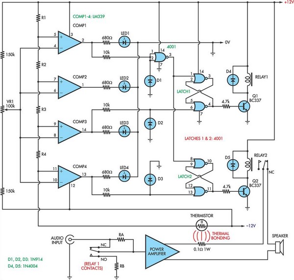
When the voltage on the non-inverting input of each comparator exceeds the voltage at its inverting input, the output transitions to a high state, activating the corresponding LED. NOR gate latches are connected to the outputs of the third...
This circuit design is a sound and light control delay switch for staircase walkway lighting, featuring high voice sensitivity. In the evening, when someone walks on the stairs, their footsteps activate the electronic meter, turning on the lights. If...
For a robot to perform its assigned tasks, a controller is necessary. This controller may be mechanical, electrical, electronic, or a combination of these. It acts as the brain of the entire system, providing the robot with its intelligence....
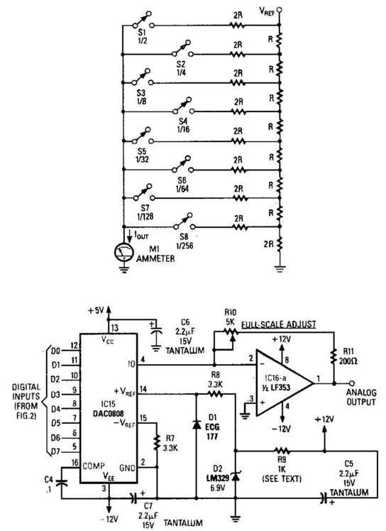
Figure A illustrates an R/2R resistor ladder. Each closed switch increases the current output. A basic channel A/D converter is depicted in Figure B. The voltage reference (D2) is shared among all channels, while the value of the dropping...
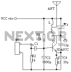
The ordinary triode 3DA87C is utilized to create a long-range FM transmitter circuit, which functions as a standard three-point oscillator circuit. This remote transmitter circuit is capable of large current emissions, achieving a range of up to 1 kilometer...
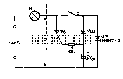
Closing the switch S allows the AC positive half-cycle to flow through diode VDI and resistor R, causing the SCR to open simultaneously at both ends of the capacitor C, which becomes fully charged. During this phase, the positive...