
12v switching power supply schematic

The 12V switching power supply is a crucial component in various electronic applications, providing a stable output voltage while efficiently converting input voltage. The schematic typically consists of several key components, including a transformer, rectifier, filter capacitor, and a switching element such as a MOSFET or IGBT.
The transformer is responsible for stepping down the input voltage to a lower level suitable for the output. In a switching power supply, the transformer operates at high frequencies, which allows for a smaller and lighter design compared to linear power supplies. The rectifier, usually implemented with diodes, converts the alternating current (AC) output from the transformer into direct current (DC).
After rectification, the filter capacitor smooths the output voltage, reducing ripple and ensuring a more stable DC output. The switching element is controlled by a pulse-width modulation (PWM) circuit, which regulates the output voltage by varying the duty cycle of the switching signal. This method enhances efficiency, as the switching element operates in either the fully on or fully off state, minimizing power loss.
Thermal management is a critical aspect of the design, as excessive heat can lead to component failure and reduced reliability. Heat sinks or active cooling methods may be employed to dissipate heat generated by the components, particularly the switching element and rectifier.
Overall, the design of a 12V switching power supply requires careful consideration of component selection, layout, and thermal management to ensure optimal performance and longevity.Hi all, I just notice that this 12v switching power supply schematic is hot, some people discuss it in top forum like dp.12v Switching Power Supply.. 🔗 External reference
Related Circuits
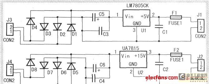
When the input voltage is between 198-242V, the average load current should be maintained at 0.5-1A, and the output voltage must remain at 15V with an error margin of less than 5%. The design and measurement of the stabilized...

A simple 16-volt switching power supply circuit can be constructed using the provided diagram, which is based on the MAX668 constant-frequency, pulse-width modulating (PWM), current-mode DC-DC controller. This integrated circuit is designed for a wide range of DC-DC conversion...
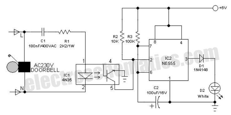
An interesting hobby circuit of a crank doorbell. The circuit is built around a 555 timer and a musical piezo buzzer. It operates using a 9-volt battery supply; a single 9-volt PP3/6F22 compact battery is sufficient to power the...
The following circuit illustrates a Power Amplifier Circuit Diagram utilizing a 2N3055 transistor. Features include a 500-ohm current and an optimal voltage of 50V. The power amplifier circuit based on the 2N3055 transistor is designed to deliver significant output power,...
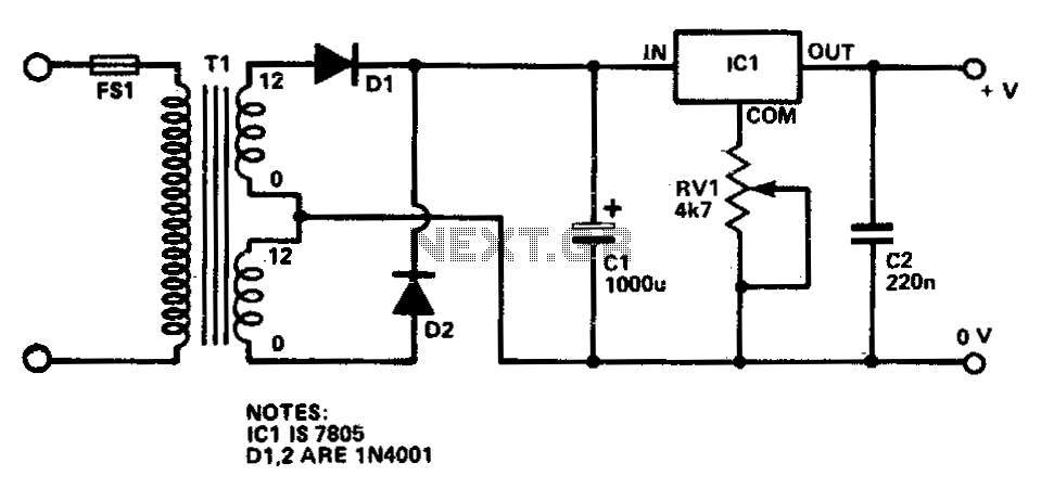
This circuit provides a regulated output voltage ranging from 5 V to 15 V DC, which can be adjusted using a preset resistor. The current output can reach up to approximately 350 mA. An integrated circuit is utilized to...
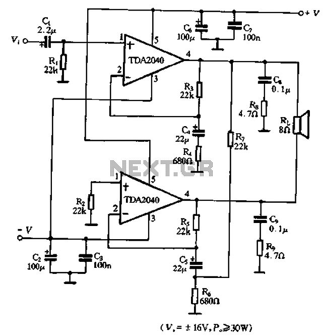
The TDA2040 is a power audio amplifier with a wider operating voltage range compared to the TDA2030, ranging from 4V to 20V. It can deliver an output power of 18W at a load of 4 ohms when supplied with...