
12V Time Delay Relay Circuit
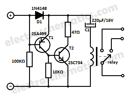
This 12V time delay relay circuit is designed to safeguard sensitive electronic devices by providing a delay before activating the connected load. It utilizes a relay to control the power supply to the device, ensuring that any transient voltage spikes are dissipated before the device is powered on.
The circuit typically includes a power supply section that converts the input voltage to the required 12V. This is often achieved using a switch-mode power supply (SMPS) which is efficient and compact, making it suitable for modern electronic applications. The relay is selected based on the load requirements, and it is crucial to ensure that it can handle the current and voltage specifications of the connected equipment.
A time delay feature is implemented using a timing circuit, which can be constructed with a resistor-capacitor (RC) network or a dedicated timer IC. When the circuit is powered on, the timing circuit begins to charge, and once it reaches a predetermined voltage level, it activates the relay. This delay allows for any initial power surges to settle, thus protecting the connected equipment from potential damage.
The circuit may also include additional components such as diodes for flyback protection, ensuring that voltage spikes generated by the relay coil do not affect the rest of the circuit. Capacitors may be added to filter out noise and stabilize the power supply.
In summary, this 12V time delay relay circuit is an effective solution for protecting sensitive electronic devices from voltage spikes, utilizing modern components and design techniques to ensure reliability and efficiency in operation.Protect your equipments with this tiny 12V time delay relay circuit. The SMPS based power supply of these modern electronic devices is vulnerable to spikes.. 🔗 External reference
Related Circuits
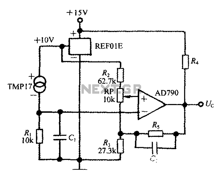
An adjustable thermostat controller circuit is widely used in everyday applications, such as for maintaining a constant temperature in soldering irons. The circuit utilizes the TMP17 sensor along with the REF01E voltage reference to ensure a stable 10V supply...
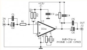
This simple circuit generates narrow pulses at a frequency of approximately 700-800 Hz. The pulses, which contain harmonics extending into the MHz range, can be injected into audio or radio-frequency stages of amplifiers and receivers for testing purposes. A...
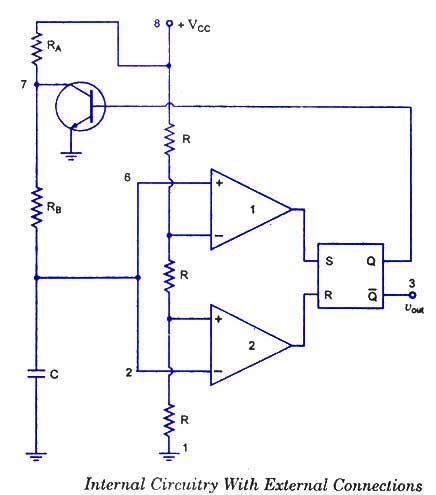
The 555 timer is a highly versatile integrated circuit that can be utilized to construct a wide variety of circuits. It can be effectively used without a detailed understanding of the function of each pin. The 555 timer is commonly...
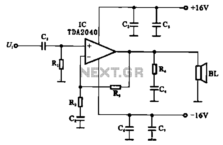
An integrated power amplifier, TDA2040 (IC), can be configured as an OCL (Output Capacitor-Less) power amplifier. The circuit, illustrated in Figure 10-10, operates using a symmetrical ±1V dual supply voltage. The OCL amplifier benefits from the positive and negative...
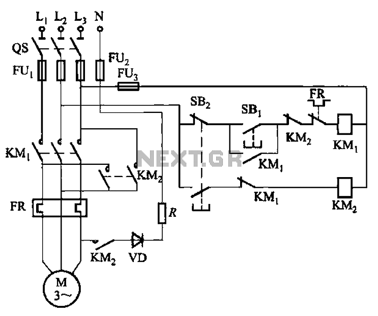
The circuit shown in Figure 3-139 utilizes a rectifier diode brake for neutral grounding in a three-phase, four-wire power supply system. The circuit employs a rectifier diode configuration to achieve effective neutral grounding, which is crucial for maintaining system stability...
The video amplifier circuit utilizes the LM359 integrated circuit, which is a dual, high-speed, programmable current mode (Norton) amplifier. This circuit is suitable for general-purpose video amplification applications. The LM359 is designed to operate as a high-speed amplifier, making it...
Warning: include(partials/cookie-banner.php): Failed to open stream: Permission denied in /var/www/html/nextgr/view-circuit.php on line 713
Warning: include(): Failed opening 'partials/cookie-banner.php' for inclusion (include_path='.:/usr/share/php') in /var/www/html/nextgr/view-circuit.php on line 713