
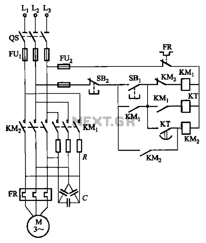
Seven one-way operation of the dynamic braking circuit

The circuit employs a rectifier diode configuration to achieve effective neutral grounding, which is crucial for maintaining system stability and safety in three-phase power systems. The rectifier diode serves as a one-way valve for current, allowing it to flow in one direction while blocking reverse current. This property is essential for preventing potential faults that could arise from ground loops or imbalances in the system.
In a standard three-phase power supply, the neutral point is typically grounded to ensure that the voltage levels remain stable and to provide a reference point for the system. The rectifier diode brake enhances this grounding method by incorporating a diode that can handle high voltage and current levels, ensuring that the grounding system remains effective even under load conditions.
The circuit may include additional components such as resistors or capacitors to filter out noise and provide stability to the rectifier operation. The design should also consider the thermal management of the diode, as excessive heat can lead to failure. Adequate heat sinking or thermal protection mechanisms should be implemented to prolong the lifespan of the diode and ensure reliable operation.
Overall, this rectifier diode brake circuit is an effective solution for neutral grounding in three-phase four-wire systems, providing enhanced safety and stability while minimizing the risk of electrical faults. Circuit shown in Figure 3-139. This circuit uses a rectifier diode rectifier brake for neutral grounding of the three-phase four-wire power supply system.
Related Circuits

The 555 integrated circuit (IC) is utilized in a delay circuit configuration. It transitions from a high to a low output state when a button (SB) is pressed. The output remains high for a specified delay period before transitioning...
The circuit depicted in Figure 3-35 demonstrates a method for starting a motor that transitions to full voltage through a step-down switching process. This approach provides an uninterruptible power supply, effectively preventing issues related to switching currents that may...
An adaptable siren generator circuit with multiple applications is presented. It is based on a 556 twin-timer chip, IC1. One timer section generates an audio tone that is directly coupled to the driver transistor, TR1. The other half of...
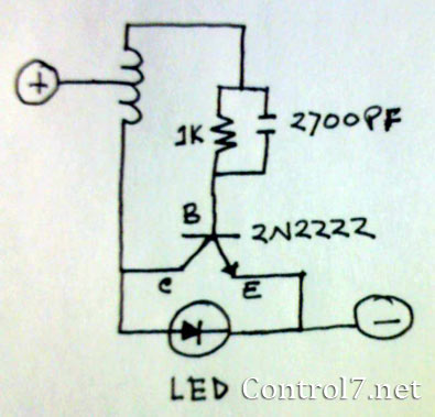
The LED is a fascinating component for amateur electronics hobbyists. The primary characteristic of an LED is that it requires a minimum of 3 volts to illuminate. Various circuits have been discovered to drive an LED using a single...

This basic tuned LC amplifier can be used with three output coupling methods: capacitive coupling output, capacitive tapped output, or link-coupled output. The tuned LC amplifier is a fundamental circuit used in various applications, including radio frequency (RF) amplification and...
Electron trajectories in a conductor are depicted in the diagrams below. When no electric field is present inside a conducting material, electrons move randomly. However, when an electric field is applied, the electric force F = qE induces a...
Warning: include(partials/cookie-banner.php): Failed to open stream: Permission denied in /var/www/html/nextgr/view-circuit.php on line 713
Warning: include(): Failed opening 'partials/cookie-banner.php' for inclusion (include_path='.:/usr/share/php') in /var/www/html/nextgr/view-circuit.php on line 713