
Adjustable thermostat controller circuit diagram created REF01E
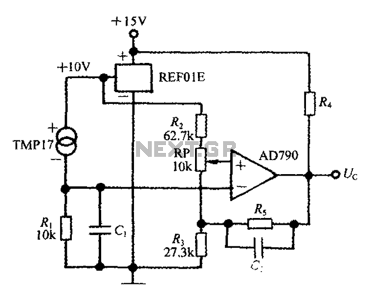
The adjustable thermostat controller circuit is designed to maintain specific temperature levels in various applications. The TMP17 temperature sensor plays a crucial role by providing accurate temperature readings. The REF01E serves as a precision voltage reference, ensuring that the circuit operates with a consistent 10V supply, which is essential for reliable performance.
Resistor R1 is strategically placed to convert the temperature reading from the TMP17 into a proportional voltage signal. This voltage signal is then fed into the AD790 voltage comparator, which functions as a threshold detector. The comparator compares the voltage corresponding to the measured temperature (t) against a predetermined set temperature (t0).
When the measured temperature reaches the set point, the output of the AD790 transitions to a low state, signaling that the desired temperature has been achieved. This output can be used to control heating elements, such as those found in soldering irons, by turning them off or on as needed to maintain the set temperature.
In summary, this adjustable thermostat controller circuit combines a temperature sensor, a precision voltage reference, and a voltage comparator to create an efficient and reliable temperature control system suitable for various applications, particularly in soldering and other temperature-sensitive processes.Adjustable thermostat controller circuit is very long use in everyday life, such as constant temperature soldering iron, as shown in FIG. TMP17 by the REF01E to provide a high degree of stability 10V supply voltage across the resistor R1 can be obtained with the measured voltage signal proportional to the temperature t. AD790 voltage comparator. Order t, t0 represent the measured value and the set value of the temperature, when t t0 when the thermostat output is low, t
Related Circuits
A stepper motor is an effective solution for achieving high-precision motion control. To operate a stepper motor, a corresponding control circuit is required. A stepper motor control circuit typically consists of several key components that facilitate the precise movement of...

This smoke detector electronic project is designed using the LM1801 and common electronic components. The smoke detector circuit diagram does not utilize ionization detection, gas sensors, or optocouplers; instead, it employs two photoresistors (LDRs) and an LED. The circuit...
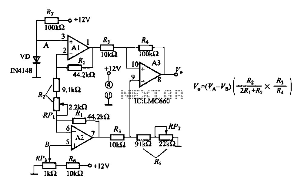
A diode IN4148 temperature circuit is presented. The circuit operates within a temperature range of -25 to 125 degrees Celsius, with an accuracy of 0.5. The core components of the operational amplifier circuit consist of four LMC660 amplifiers. It...
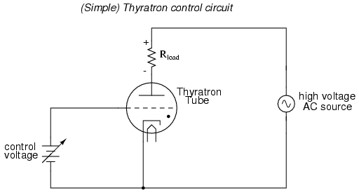
An often neglected area of study in modern electronics is that of tubes, more precisely known as vacuum tubes or electron tubes. Almost completely overshadowed by semiconductor, or "solid-state" components in most modern applications, tube technology once dominated electronic...
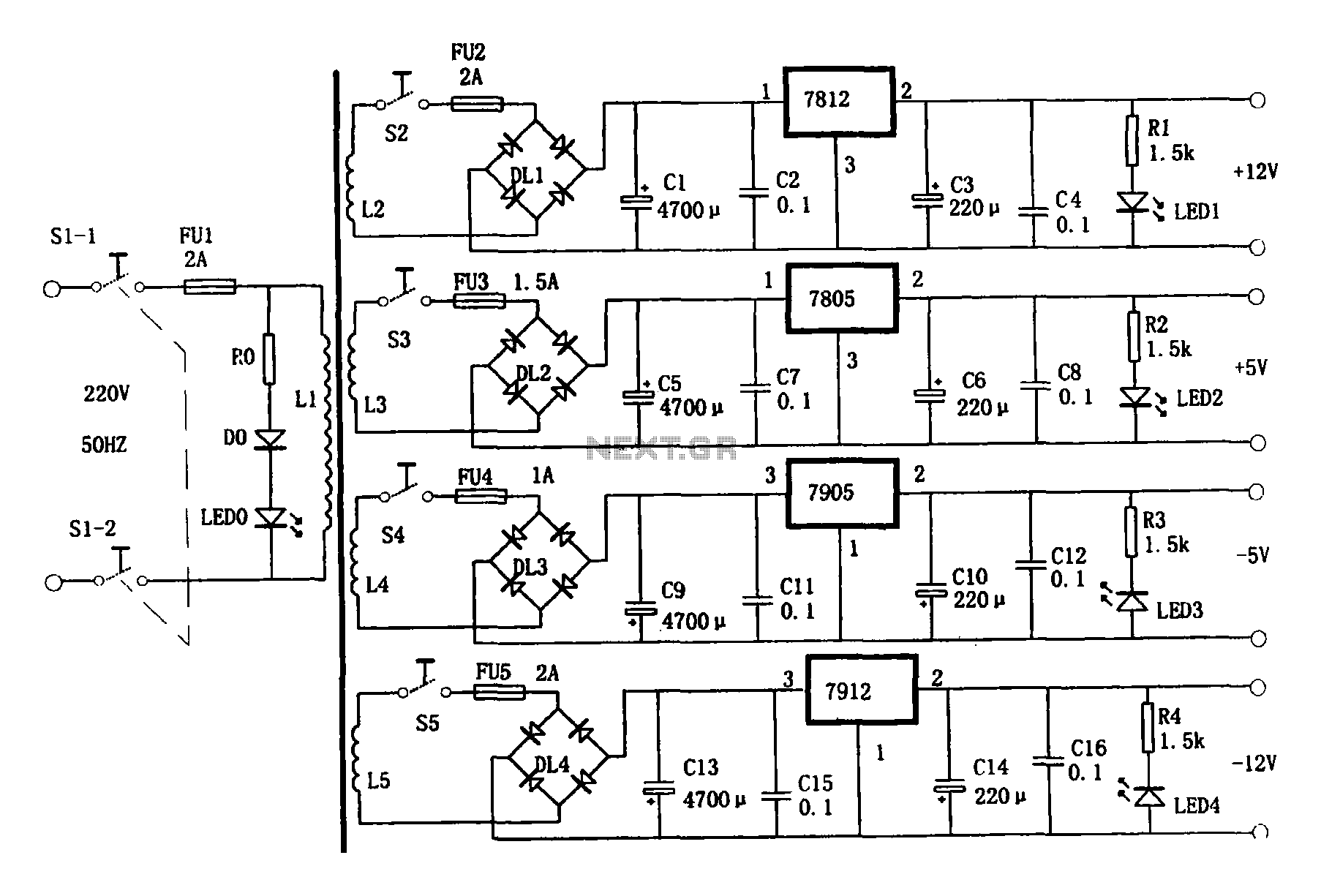
This document presents a multi-output power supply circuit. The circuit utilizes the secondary winding of a transformer and incorporates four voltage regulators: 7812, 7805, 7905, and 7912, providing independent output voltages of +12V, +5V, -5V, and -12V, respectively. Each...
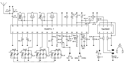
The TEA5711 datasheet indicates that essential functions, including the AM and FM front end, AM detector, and FM stereo output stages, are integrated within the TEA5711 AM/FM stereo radio circuit. The accompanying circuit diagram illustrates the TEA5711T in conjunction...
Warning: include(partials/cookie-banner.php): Failed to open stream: Permission denied in /var/www/html/nextgr/view-circuit.php on line 713
Warning: include(): Failed opening 'partials/cookie-banner.php' for inclusion (include_path='.:/usr/share/php') in /var/www/html/nextgr/view-circuit.php on line 713