
12V to 3V Car adapter
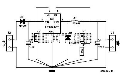
The LT1074CT briskly switches the supply voltage on and off in response to the signal applied to its F/B input, to the extent that the average output voltage is at the required level. The values of potential divider resistors R1-R3 have been chosen to attenuate the output voltage so that there is 2.5 V at the F/B pin. The difference between the attenuated output voltage and the internal 2.5-V reference is used to control the modulation effect of the switcher.
Components R2 and C2 provide frequency stabilization for the feedback loop. Inductor L1 along with the LT1074CT form the main switching components, while C1 provides decoupling for the output load. The 3-V output voltage is taken from screw terminal J1. With this circuit built, boxed up and installed in your car, you can look forward to possibly your first ‘quiet’ long car journey.
The LT1074CT is a versatile step-down switching regulator that efficiently converts higher voltages to lower voltages, making it ideal for powering low-voltage devices from a car's electrical system. The input voltage range accommodates the typical automotive environment, which can vary from approximately 10.5 volts to 14.5 volts, depending on the vehicle's charging system.
The circuit's design includes essential components for stability and reliability. The use of a fused cigarette lighter plug is crucial for safety, protecting the circuit from potential overcurrent conditions. The diode D2 serves as a safeguard against reverse polarity, ensuring that the circuit components are not damaged if the power supply is connected incorrectly.
In the feedback loop, the resistors R1, R2, and R3 are carefully selected to set the output voltage to 3 volts. The LT1074CT's feedback mechanism compares the divided output voltage to its internal reference voltage, adjusting the duty cycle of the switching signal to maintain a stable output. Capacitor C2, in conjunction with R2, forms a compensating network that helps stabilize the feedback loop against oscillations, which can be crucial for maintaining output voltage stability under varying load conditions.
Inductor L1 is a key component in the energy transfer process, storing energy when the switch inside the LT1074CT is closed and releasing it to the output when the switch opens. The output capacitor C1 smooths the voltage at the output terminal J1, ensuring that the connected devices receive a clean and stable 3-volt supply, which is particularly important for sensitive electronics like personal hi-fi systems and handheld gaming devices.
This circuit design not only addresses the power requirements of low-voltage devices but also considers the operational environment of a vehicle, ensuring that it can function reliably during long journeys. The overall configuration promotes efficient power conversion with minimal noise, making it suitable for use in a car where noise levels can be a concern.This 3 volts Car Adapter circuit is based on a standard LT1074CT switching regulator IC. The schematic shows the LT1074CT used as a positive step-down or ‘buck’ converter. The ‘switcher’ is used to convert a +12-volt car battery voltage down to +3 volts for use with the personal hi-fi’s and handheld games for the author’s two boisterous children on long car journeys. Note at under ten years of age, children will rarely be hi-fi aficionado’s and are generally not concerned with any noise generated by the ‘switcher ‘circuit.
The circuit is connected to the car +12-V system via the cigarette lighter socket — is advisable to use a fused version of the cigarette lighter plug. The +12-V arrives on the board via screw- terminal block J2. Diode D2 provides a reverse voltage protection, while C3 decouples the input to the switcher IC. The LT1074CT briskly switches the supply voltage on and off in response to the signal applied to its F/B input, to the extent that the average output voltage is at the required level.
The values of potential divider resistors R1-R3 have been chosen to attenuate the output voltage so that there is 2.5 V at the F/B pin. The difference between the attenuated output voltage and the internal 2.5-V reference is used to control the modulation effect of the switcher.
Components R2 and C2 provide frequency stabilisation for the feedback loop. Inductor L1 along with the LT1074CT form the main switching components, while C1 provides decoupling for the output load. The 3-V output voltage is taken from screw terminal J1. With this circuit built, boxed up and installed in your car, you can look forward to possibly your first ‘quiet’ long car journey.
🔗 External reference
Related Circuits
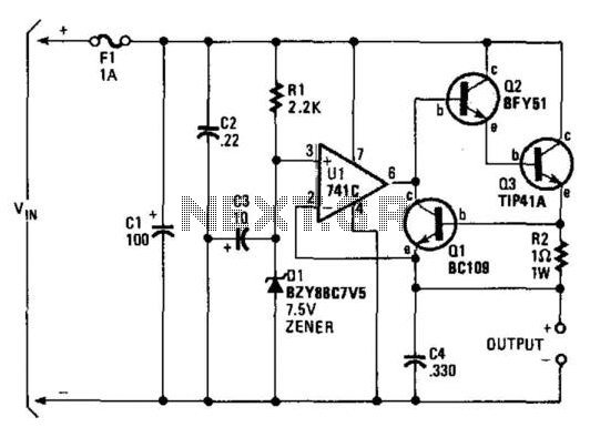
A regulator enables the powering of a 7.5-V cassette recorder or other devices from a 12-V DC automotive system. The circuit can provide approximately 600 mA of current. Q3 requires a heatsink due to its potential to dissipate up...
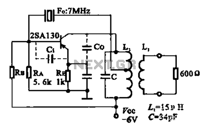
The 2SA130 transistor is used in an oscillator circuit with an oscillation frequency of 7 MHz. The power supply voltage is 6V, and the load is a frequency-selective resonant circuit with a quality factor of 600. The circuit utilizes the...
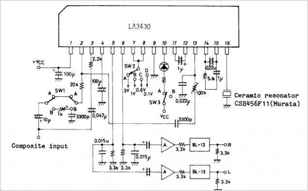
The LA4165M Recording-Playback Integrated Circuit (IC) integrates the necessary functions to design recording and playback systems, as well as motor control circuits, for both micro and standard cassette tape recorders into a single chip. It features automatic audio input...
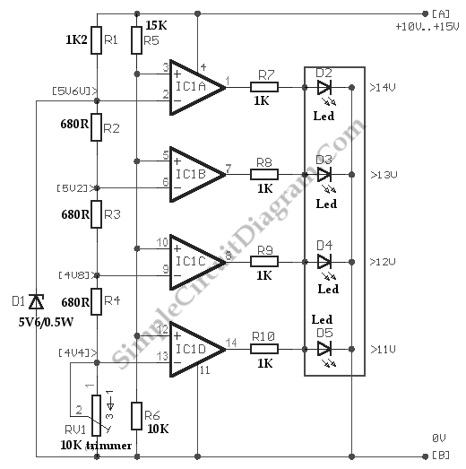
Below is a comparator circuit that can measure the voltage of a car battery in 1-volt steps. The voltage indication is achieved through a comparison mechanism. The described comparator circuit is designed to accurately measure and indicate the voltage level...
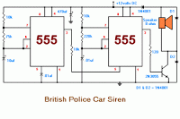
The 555 timer on the right is configured as an alarm sound generator, while the second 555 timer on the left operates as a 1 Hz astable multivibrator. The output from the left timer modulates the frequency of the...
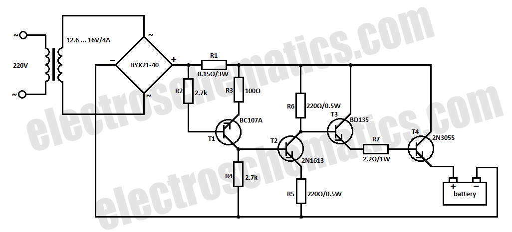
The car battery charging current is automatically limited to 4.2A. If there is a 600mV voltage on R1 (indicating 4A flowing through it), the T1 transistor begins to conduct. This prevents excessive charging current as the base current of...
Warning: include(partials/cookie-banner.php): Failed to open stream: Permission denied in /var/www/html/nextgr/view-circuit.php on line 713
Warning: include(): Failed opening 'partials/cookie-banner.php' for inclusion (include_path='.:/usr/share/php') in /var/www/html/nextgr/view-circuit.php on line 713