
Voltmeter With LED For Car Battery
The described comparator circuit is designed to accurately measure and indicate the voltage level of a car battery in increments of one volt. It utilizes a voltage comparator, which is a device that compares two input voltages and outputs a digital signal based on their relative magnitudes.
The circuit typically consists of a reference voltage source, which establishes the threshold levels for the comparison, and the car battery voltage is fed into one of the comparator's inputs. The other input is connected to the reference voltage, which can be set at intervals corresponding to the voltage levels of interest (e.g., 0V, 1V, 2V, etc.).
When the voltage from the car battery exceeds the reference voltage, the comparator outputs a high signal, indicating that the battery voltage is above the set threshold. Conversely, if the battery voltage is below the reference level, the output will be low. This output can be connected to an LED indicator or an LCD display to provide a visual representation of the battery voltage level.
For enhanced functionality, multiple comparators can be used in a ladder configuration to cover a wider voltage range. Each comparator can be set to a different reference voltage, allowing for a more granular indication of the battery's state. Additionally, hysteresis can be introduced into the circuit to prevent rapid toggling of the output due to minor fluctuations in battery voltage.
Power supply considerations are crucial for the comparator circuit; it should operate within the voltage rating of the components used, ensuring reliable performance. Furthermore, proper filtering and protection measures should be implemented to safeguard the circuit from voltage spikes or noise that may be present in automotive environments.
Overall, this comparator circuit serves as an effective solution for monitoring the voltage of a car battery, providing clear and immediate feedback on its state of charge.Below is a comparator circuit which is can measure with step of 1 volt, the voltage of car battery. The indication of voltage is done by comparison of? . 🔗 External reference
Related Circuits

A simple circuit for a 10 LED roulette wheel is presented. Pressing the button initiates the LEDs in a rotational sequence that starts at full speed and gradually decelerates until it halts at a randomly selected LED. The randomness...
The tank circuit consisting of capacitor C2 and inductor L1 is utilized to tune the transmitter. The antenna is coupled to the transmitter through capacitor C3 and can be either a telescopic antenna or a length of hookup wire....
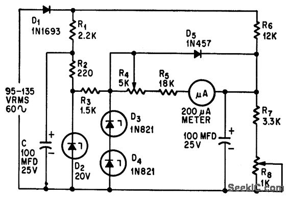
This circuit measures alternating current (AC) voltages in the range of 95 to 135 volts with an accuracy of 0.6%, utilizing a standard meter that has a 2% accuracy rating. The circuit employs Zener diodes to provide a stable...

The Over-the-Top type of operational amplifier is ideal for use as a current sensor for battery charger applications. The design described here can be used with chargers for rechargeable batteries (Lead/acid or NiCd, etc.). The 5 V operating supply...
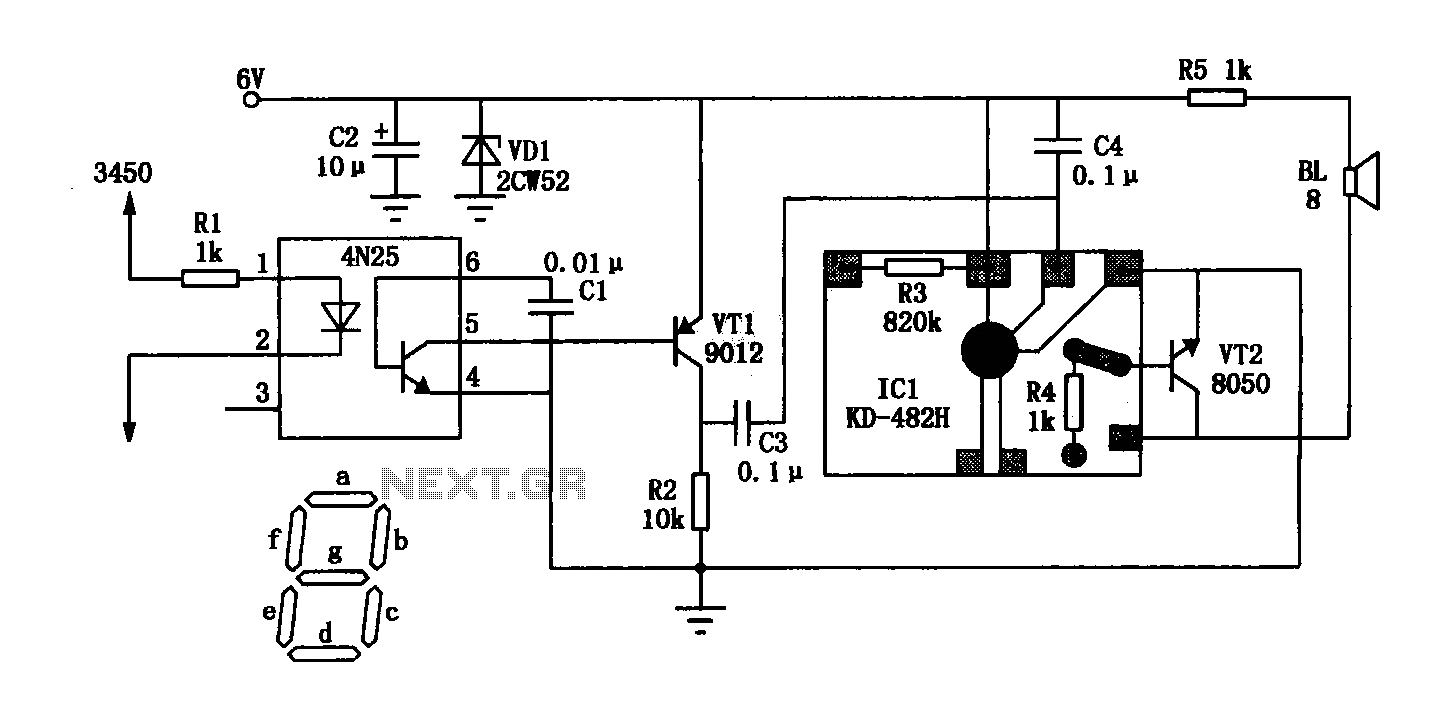
The General Dynamic LED digital clock lacks a timekeeping function, but by adding a simple circuit, it can incorporate this feature. The integrated circuit (IC) includes a programmable mute function, which is inactive from 23:00 to 5:00 to avoid...
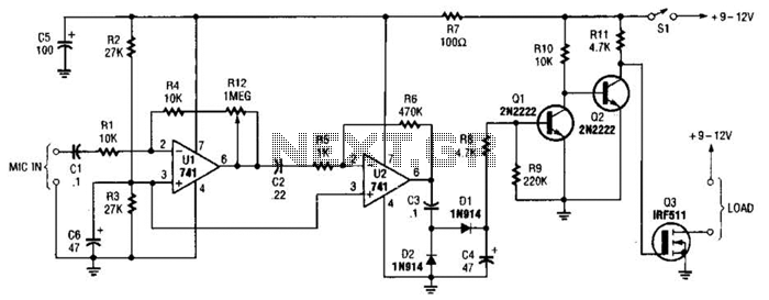
This audio-controlled switch integrates a pair of 741 operational amplifiers, two 2N2222 general-purpose transistors, an hcxFET, and several supporting components into a circuit capable of activating devices such as a tape recorder, a transmitter, or virtually any sound-activated equipment. The...
Warning: include(partials/cookie-banner.php): Failed to open stream: Permission denied in /var/www/html/nextgr/view-circuit.php on line 713
Warning: include(): Failed opening 'partials/cookie-banner.php' for inclusion (include_path='.:/usr/share/php') in /var/www/html/nextgr/view-circuit.php on line 713