
Latest British Police Car Siren circuit
The circuit consists of two 555 timer integrated circuits (ICs), each serving a distinct purpose. The left 555 timer is set up in an astable configuration, generating a continuous square wave output at a frequency of 1 Hz. This output serves as a control signal that modulates the frequency of the right 555 timer, which is configured as a monostable or astable sound generator, depending on the specific design requirements.
The modulation of the right timer's frequency is achieved by connecting the output of the left timer to the control voltage pin (pin 5) of the right timer. When the left timer outputs a high signal, the frequency of the right timer increases to 550 Hz, and when it outputs a low signal, the frequency decreases to 440 Hz. This alternating frequency generation creates a distinctive alarm sound that can be used in various applications.
The 2N3055 transistor is employed as a power amplifier to drive a loudspeaker. It is connected to the output of the right 555 timer, allowing the amplified sound signal to be delivered to the speaker. The transistor's base is connected to the output of the 555 timer, while the collector is connected to the loudspeaker, and the emitter is grounded. This configuration ensures that the audio signal is sufficiently amplified to be audible when emitted from the loudspeaker.
Overall, this circuit is an excellent project for novice hobbyists, providing a practical introduction to timer circuits, frequency modulation, and audio amplification. It demonstrates fundamental concepts in electronics while allowing for experimentation and learning through hands-on experience.The 555 on the right is wired as an alarm sound generator and the second 555 timer on the left is a 1 Hz astable multivibrator. The output of the left timer is to modulate the frequency of the right timer. This process will cause the right timers frequency to alternate between 440Hz and 550Hz at a 1 Hz cyclic rate.
The transistor 2N3055 is used to amplify the sound signal to the loudspeaker. This circuit should be nice for newbie hobbysts. 🔗 External reference
Related Circuits

By utilizing a 556 dual timer, with IC1A functioning as a waveshaper and IC1B as a pulse generator, a pulse width range of 10:1 can be achieved. This circuit can be triggered using a sine wave. The circuit operates on...
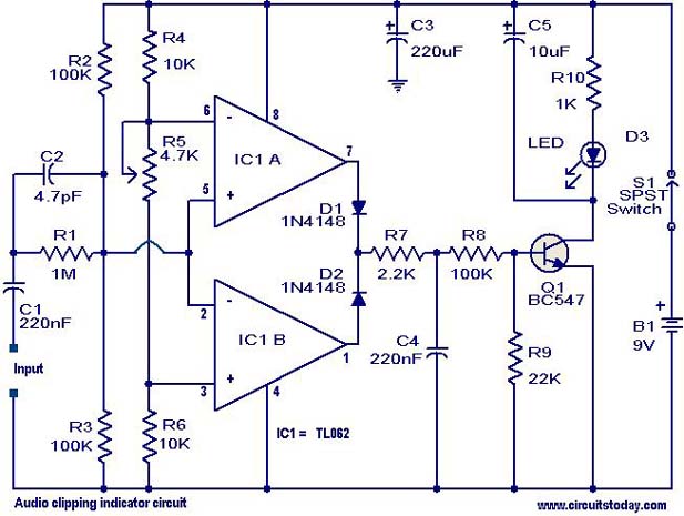
This circuit is designed to detect clipping in a specific waveform. Clipping occurs when the amplitude of a waveform decreases before reaching its expected limit. The circuit activates an LED as an indication that the tested signal is experiencing...
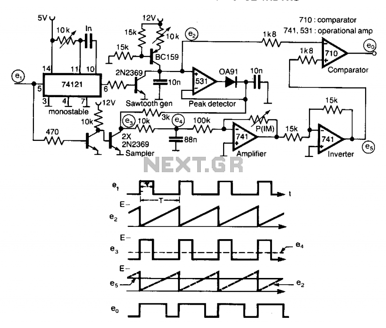
A circuit designed to multiply the width of incoming pulses by a factor that can be greater or less than unity is straightforward to construct. It features a single adjustable potentiometer for selecting the multiplying factor. This factor is...
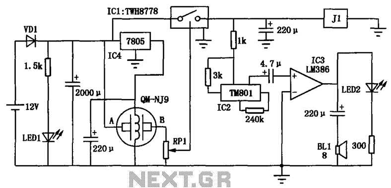
The alcohol detection alarm controller circuit is illustrated in the figure. It utilizes the QM-NJ9 alcohol gas sensor, which detects the presence of alcohol vapors. When alcohol is detected, the resistance between the AB-QM-NJ9 decreases, causing the wiper of...
Here is a simple circuit which can be used for decoration purposes or as an indicator. Flashing or dancing speed of LEDs can be adjusted and various dancing patterns of lights can be formed. The circuit consists of two...
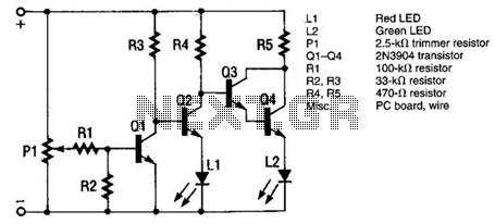
The monitor functions as a basic voltage comparator, utilizing a car battery as its power source. The input voltage to the comparator is adjusted using potentiometer PI. This adjustment ensures that the green LED L2 illuminates when the alternator...
Warning: include(partials/cookie-banner.php): Failed to open stream: Permission denied in /var/www/html/nextgr/view-circuit.php on line 713
Warning: include(): Failed opening 'partials/cookie-banner.php' for inclusion (include_path='.:/usr/share/php') in /var/www/html/nextgr/view-circuit.php on line 713