
12vac to 220vac inverter circuit
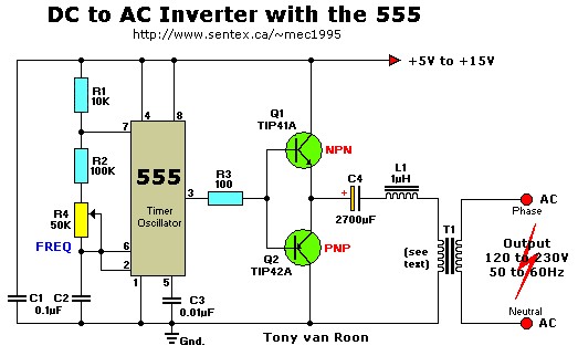
This inverter circuit utilizes a 555 timer IC in astable mode to produce a square wave signal, which is essential for driving the power transistors Q1 and Q2. The frequency adjustment through potentiometer R4 allows for fine-tuning of the output frequency, which is critical for applications requiring precise line frequency operation.
Transistors Q1 and Q2 serve as the amplification stage, switching the current through the primary winding of transformer T1. The transformer is configured such that its secondary winding provides the necessary voltage increase from 12V DC to 220V AC. The choice of transformer is crucial; a filament transformer is typically used due to its ability to handle the necessary power levels and provide the required turns ratio for voltage step-up.
Capacitor C4 and inductor L1 form a low-pass filter that smooths the output waveform. This filtering is vital to convert the square wave output from the transistors into a more sinusoidal waveform, which is generally required for most AC applications. The filter helps to reduce harmonic distortion, improving the quality of the AC output.
Careful selection of component values, particularly for the transformer and filter components, is essential for optimal performance of the inverter. The circuit design must ensure that the transformer can handle the expected load, and the filter components must be chosen to achieve the desired output characteristics while maintaining efficiency. This inverter circuit can be employed in various applications, including powering small appliances or serving as a backup power source.This simple 12VDC to 220VAC inverter circuit produces an AC output at line frequency and voltage. The 555 is configured as a low-frequency oscillator, tunable over the frequency range of 50 to 60 Hz by Frequency potentiometer R4. The 555 feeds its output (amplified by Q1 and Q2) to the input of transformerT1, a reverse-connected filament transformer with the necessary step-up turns ratio.
Capacitor C4 and coil L1 filter the input to T1, assuring that it is effectively a sine wave. Adjust the value of T1 to your voltage. 🔗 External reference
Related Circuits
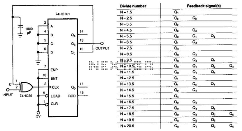
This circuit divides the input signal by +1/2 instead of dividing by an integer. With the feedback connections as illustrated in the figure, the circuit effectively divides by 3.5. Point C ultimately determines when the input triggers the 74HC161...
This circuit consists of a 6 Zone Alarm system with an LED display. The alarm system features 6 independent zones and includes a 7-segment LED display, along with one timed entry/exit zone. The 6 Zone Alarm system is designed to...
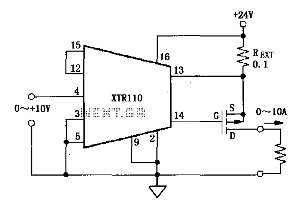
When the output current exceeds 40mA, the XTR110 requires the use of an external resistor (REXT) instead of the internal 50-ohm resistor (R9). REXT should be connected between pin 13 and pin 1. The value of REXT is determined...
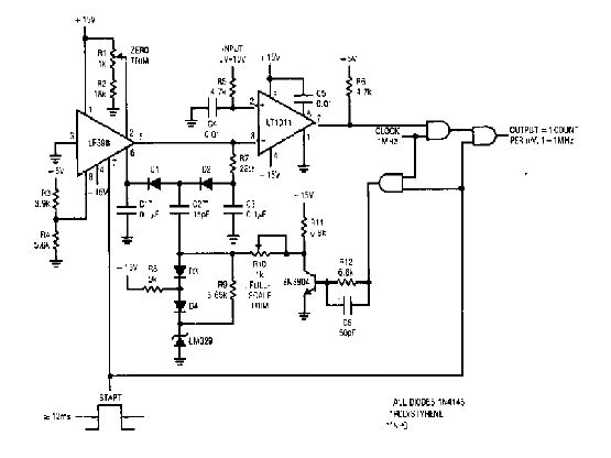
The simple 4-digit converter circuit has an output count of 1, designed to operate within a frequency range of f-IMHz to 10.000. All diodes used in the circuit are IN4146, and the capacitors are made of `POLYSTYRENE` NPO. The...

This is a simple circuit design for a video transmitter capable of radiating signals up to 50 meters. The video transmitter can be connected to a camera as a source and allows viewing on a VHF channel analog television....
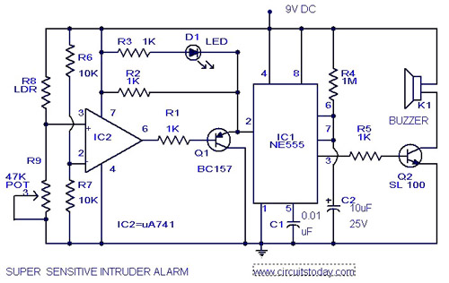
The circuit diagram represents an ultra-sensitive intruder alarm. A shadow from an intruder passing nearby is sufficient to trigger the alarm. The operational amplifier IC2 (uA 741) is configured as a sensitive comparator, with its set point determined by...
Warning: include(partials/cookie-banner.php): Failed to open stream: Permission denied in /var/www/html/nextgr/view-circuit.php on line 713
Warning: include(): Failed opening 'partials/cookie-banner.php' for inclusion (include_path='.:/usr/share/php') in /var/www/html/nextgr/view-circuit.php on line 713