
vhf video transmitter circuit

The video transmitter circuit is designed to convert video signals from a camera into a radio frequency (RF) signal that can be transmitted over a distance of up to 50 meters. The circuit's core functionality relies on the selected transistor, which amplifies the video signal for effective transmission. The BC548 transistor is a popular choice due to its general-purpose nature and suitability for low-frequency applications, while the BF199 can be used for higher frequency operations.
The circuit's power supply is straightforward, utilizing a 9V battery, which provides adequate voltage for the components involved. The use of surface-mount device (SMD) components allows for a more compact design, which is beneficial for mobile or space-constrained applications.
The coil L1 is a critical part of the circuit, consisting of 5 turns of wire with a diameter of 8 mm. The choice of wire gauge between 0.3 mm and 0.5 mm is essential, as it impacts the coil's inductance and the overall performance of the transmitter. The antenna, a simple 50 cm cable, acts as the radiating element, allowing the RF signal to propagate effectively.
To fine-tune the operational frequency of the transmitter, a trimmer capacitor of 22 pF is incorporated. Adjusting this capacitor allows the user to modify the resonant frequency of the circuit, ensuring optimal transmission on the desired VHF channel. This feature is particularly useful for avoiding interference with other signals and for compliance with local broadcasting regulations.
Overall, this video transmitter circuit is a practical solution for short-range video transmission applications, combining simplicity in design with effective performance.This is a simple design circuit for transmitter video. This circuit can radiate as far as 50m. This video transmitter can be used with the camera as a source. You can view them on VHF channel analog TV. Supply voltage to the transmitter can use 9V battery. This is the figure of the circuit. Transistor components that are used for a video transmitt er is BC548 or you can use another type of transistor BF199. Meanwhile, other passive components used SMD type. For winding coil L1 is 5 Turns 8 mm in diameter and use wire AWG 0. 3-0. 5 mm. Once you up the circuit this video transmitter, antenna use as a cable along the 50 cm. To determine the frequency of work, turn the trimmer capacitor 22 pf accordance with the frequency that you want. 🔗 External reference
Related Circuits
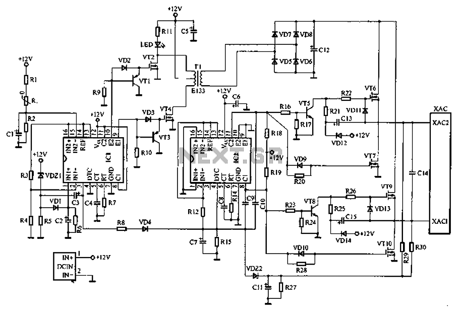
Car inverter specifications include an input voltage range of DC 10V to 14.5V, output voltage of AC 200V to 220V with a tolerance of 10%, output frequency of 50Hz with a tolerance of 5%, and an output power range...
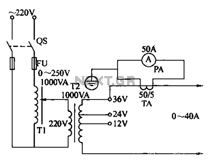
Electricians sometimes use overcurrent relays, thermal relays, and other devices to perform periodic overcurrent checks with a current generator. A secure running lights transformer, voltage regulator, and meter can be constructed using a small electric current generator. The homemade...
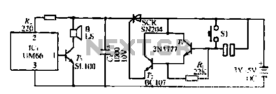
A few custom integrated circuits began to play music. When the song ends, no electricity flows through the thyristor, which then cuts off the light, causing the phototransistor to activate. The system is designed with a touchpad; each touch...
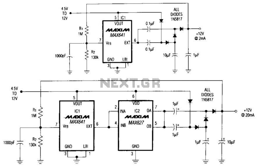
In conventional applications, switching-regulator integrated circuits (ICs) regulate the output voltage (VQVT) by controlling the current through an external inductor. However, the IC in configuration A utilizes a diode-capacitor network in place of the inductor, providing comparable performance for...
Electronics tutorial on mesh current analysis and examples of mesh analysis used to analyze complex electrical circuits in DC theory. Mesh current analysis is a powerful technique used in circuit analysis to determine the currents flowing in the loops of...
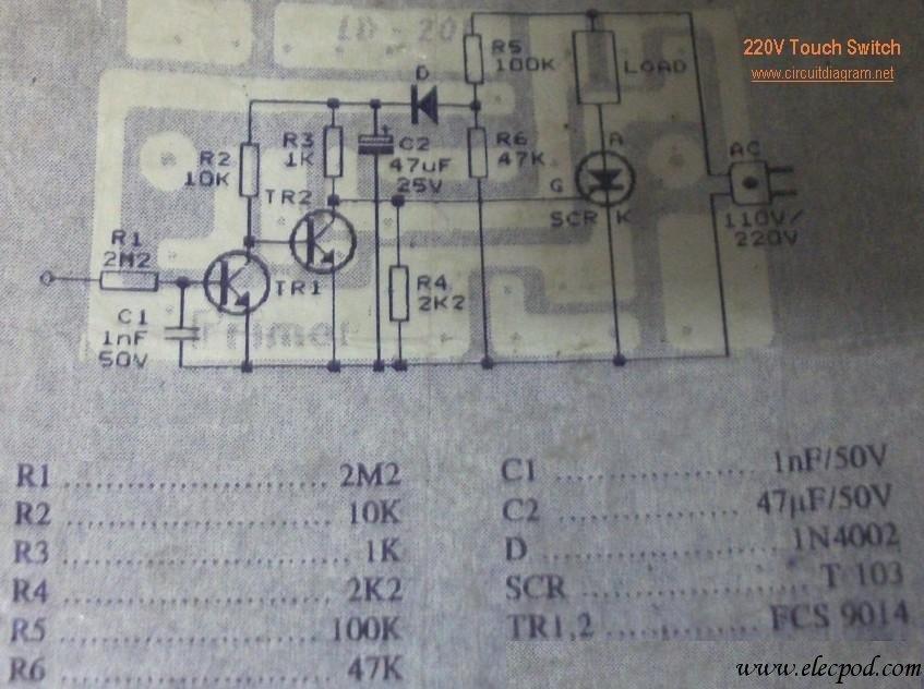
This circuit is connected directly to a 220V home electrical installation. The LOAD in the schematic diagram above represents an electronic device that consumes 220V AC current. The circuit operates by interfacing directly with the 220V AC mains supply, which...
Warning: include(partials/cookie-banner.php): Failed to open stream: Permission denied in /var/www/html/nextgr/view-circuit.php on line 713
Warning: include(): Failed opening 'partials/cookie-banner.php' for inclusion (include_path='.:/usr/share/php') in /var/www/html/nextgr/view-circuit.php on line 713