
12W Audio Power Amplifier
The 12W audio power amplifier circuit is designed to provide high-quality audio amplification in a compact form factor. This amplifier is capable of delivering up to 12 watts of output power, making it suitable for driving small speakers or as part of a portable audio solution. The circuit typically utilizes a Class AB configuration, which balances efficiency and sound fidelity, ensuring minimal distortion and high linearity across the audio spectrum.
Key components of the circuit include a differential input stage, which enhances signal integrity and reduces noise. The use of transistors or operational amplifiers in the input stage allows for a wide dynamic range and improved signal-to-noise ratio. The output stage generally employs complementary push-pull transistor pairs, which contribute to the amplifier’s ability to handle varying loads while maintaining sound quality.
Power supply requirements for the circuit are generally modest, often operating within a range of 12 to 24 volts DC. This allows for compatibility with common battery-powered applications or standard power supply units. Capacitors are strategically placed throughout the circuit to filter power supply noise and stabilize the output, while resistors are used to set gain levels and provide feedback for improved performance.
Overall, the 12W audio power amplifier circuit is a robust solution for those seeking high-quality audio amplification in a small package, making it ideal for DIY audio projects, portable devices, or compact audio systems.12W Audio Power Amplifier Circuit Diagram. Features: small power amplifier, very good quality of sound, combines a completed very good quality .. 🔗 External reference
Related Circuits
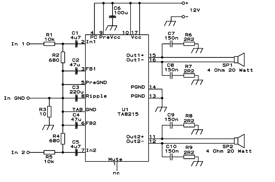
This circuit is designed as a stereo BTL (Bridge-Tied Load) 15W audio power amplifier using the TA8215 integrated circuit developed by Toshiba. Two TA8215 ICs are utilized in this configuration to achieve four output channels, with each IC providing...
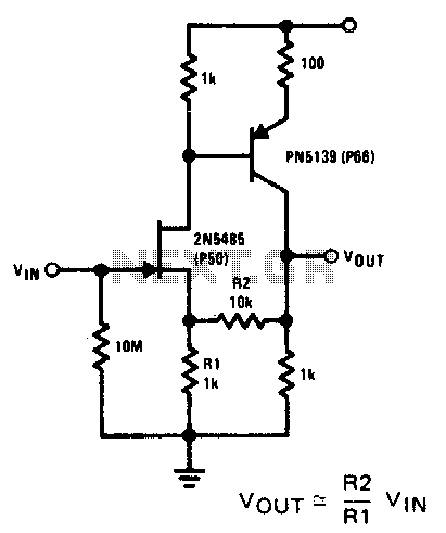
This compound series-feedback circuit provides high input impedance and stable wide-band gain for general-purpose video amplifier applications. The compound series-feedback circuit is designed to achieve high input impedance, which is essential for minimizing loading effects on the preceding stage of...
A lens is a specialized perspective on the content within a repository. It can be considered a sophisticated type of list that enables users to view content from the viewpoint of trusted organizations and individuals. A lens in this context...
Utilize this FM antenna amplifier in locations where the reception of FM stations is poor. This circuit is specifically designed for this purpose. The FM antenna amplifier circuit is engineered to enhance signal strength for FM radio stations, particularly in...
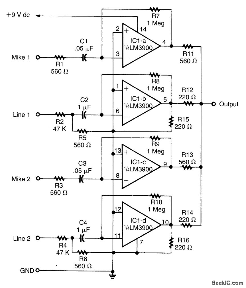
This circuit is designed around an LM3900 quad operational amplifier, which combines two line inputs and two microphone inputs, summing them at the output terminal. Resistors R7 through R10 can be adjusted to vary the gain, approximately +23 dB. The...
This weblog discusses electronic circuit schematics, PCB design, DIY kits, and electronic project diagrams. The 1K resistors in the circuit are significant as they allow the LEDs to activate at different audio levels. While these resistors can be modified,...