
FM antenna amplifier circuit
The FM antenna amplifier circuit is engineered to enhance signal strength for FM radio stations, particularly in areas with weak reception. The primary components of this circuit typically include a low-noise amplifier (LNA), an antenna input, a power supply, and output connections for the FM tuner.
The circuit operates by receiving the weak radio frequency (RF) signals from the antenna and amplifying them to a level suitable for processing by the FM tuner. The LNA is crucial in this configuration, as it minimizes noise while boosting the signal, ensuring that the quality of the audio output is preserved.
Powering the circuit generally requires a stable DC voltage, often supplied by a battery or an external power adapter. The design may also include filtering components to eliminate unwanted frequencies and ensure that only the desired FM signals are amplified.
The output of the amplifier connects directly to the FM tuner, allowing for improved sound quality and clarity. Proper grounding and shielding techniques should be implemented to prevent interference from other electronic devices.
Overall, this FM antenna amplifier circuit is an effective solution for enhancing FM reception, making it a valuable addition for users experiencing signal issues in their area.Use this fm antenna amplifier in areas where the signal reception of FM stations is too bad. This circuit is just the right thing to do it. It is designed. 🔗 External reference
Related Circuits
A thermistor positioned as indicated creates a heat-activated sensor. Variations in temperature will modify the output of the operational amplifier, triggering the relay and illuminating the LED. Reversing the placement of the thermistor and the 47k resistor converts the...
This inverter is very easy to construct, reliable, and even powerful enough to light up a 15W fluorescent tube (if you cool your transistor well). The only hard-to-find piece of this baby is the so-called yellow inverter transformer. It's...
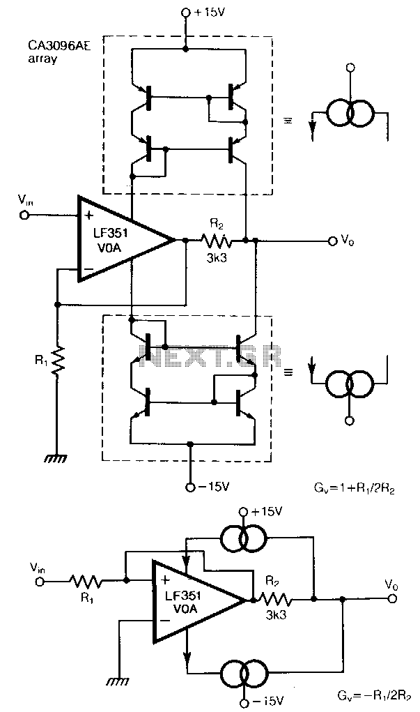
The traditional restriction of constant gain-bandwidth products for a voltage amplifier can be overcome by employing feedback around a current amplifier. Two current mirrors, constructed from transistors in a CA3096AE array, effectively turn the LF351 operational amplifier into a...
The core component of this circuit is the 555 timer IC. The alert sound does not stop immediately when the switch is activated; instead, it ceases automatically after a predetermined time period, which is set by the resistance of...
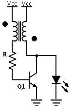
Previously, a boost circuit was tested that enables the powering of a 3 V LED using a discharged battery (approximately 1 V or lower). This circuit consists of a single transistor, one resistor, and a small transformer with a...
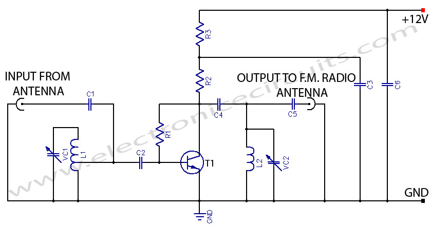
This FM booster allows for clear reception of programs from distant FM stations. The circuit features a common-emitter tuned RF preamplifier utilizing the VHF/UHF transistor 2SC2570 (only labeled as C2570 on the transistor body). The input coil L1 is...