
Operational Amplifiers and Signal Conditioning
A lens in this context serves as a filtering mechanism that organizes and presents information tailored to the preferences and trust levels of the user. This functionality can be particularly useful in environments where access to vast amounts of data can be overwhelming. By implementing a lens, users can streamline their information consumption, focusing solely on the content deemed relevant and credible by their selected sources.
In electronic schematic terms, the concept of a lens can be likened to a selective filter circuit that processes input signals based on predefined criteria. Such a circuit could be designed using operational amplifiers (op-amps) configured in a way to allow only specific frequency ranges or signal types to pass through while attenuating or blocking others. For instance, a band-pass filter could be employed to isolate signals within a certain frequency range, analogous to how a lens isolates specific content based on user-defined parameters.
The implementation of a lens circuit may involve several components, including resistors, capacitors, and inductors, arranged to form the desired filter characteristics. The design would require careful consideration of component values to achieve the appropriate cutoff frequencies and gain levels, ensuring that the output signal accurately reflects the intended selection of input data.
In summary, the lens concept can be effectively translated into electronic design principles, showcasing the importance of filtering and selective representation in both information management and electronic signal processing.A lens is a custom view of the content in the repository. You can think of it as a fancy kind of list that will let you see content through the eyes of organizations and people you trust. 🔗 External reference
Related Circuits
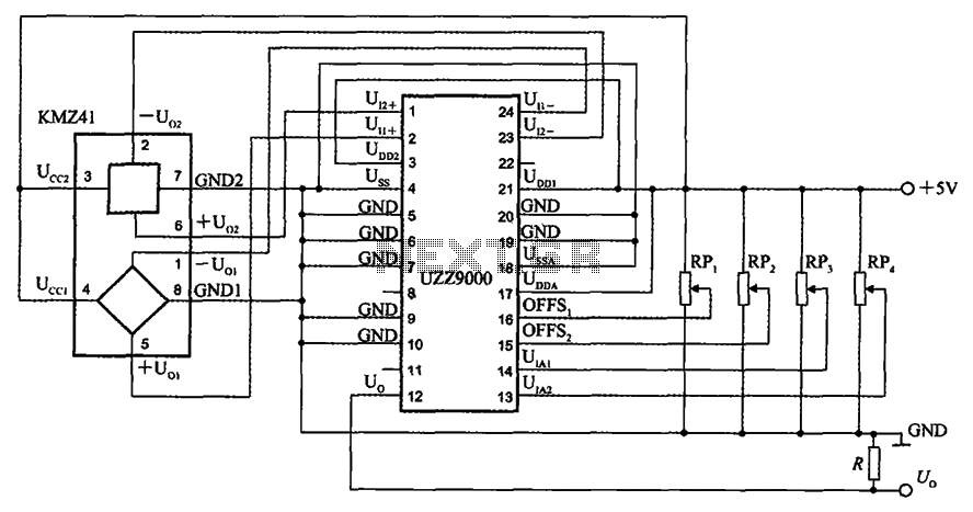
The UZZ9000 KMZ41 detection circuit is configured based on the voltage output type and angle. It operates with a +5V power supply. Potentiometers RP1 and RP2 are used for offset voltage adjustment, while potentiometers RP3 and RP4 are utilized...
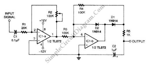
A signal averager circuit can be formed by an amplifier and active signal rectifier, which is implemented using two operational amplifiers in this circuit. The signal averager circuit utilizes two operational amplifiers (op-amps) to achieve signal averaging through amplification and...
The volt-ampere characteristics of a tunnel diode exhibit an S-shaped curve. The peak current point, referred to as point P, represents the maximum current, while the valley point, denoted as point V, indicates the minimum current. Key parameters of...
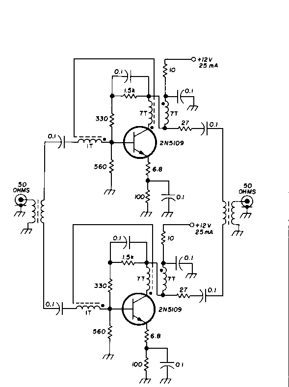
This diagram originates from the Progressive Communications Receiver featured in most recent ARRL Handbooks. The amplifier is utilized wherever an intermediate frequency (IF) amplifier is necessary. W6BKY has published an article on Hamradio-online that details the construction of this...
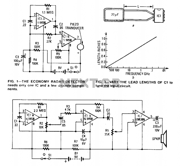
The circuit can be tuned to respond to signals between 50 MHz and 500 GHz. The economy model is illustrated in Figure 1, while the deluxe model is depicted in Figure 2. The first operational amplifier (op-amp) in each...
This is a circuit that ensures that you can connect two amplifiers together so you get more power. When called in bridge linking two amplifiers plus you can link the outputs of the amplifiers to the speaker. One of...
Warning: include(partials/cookie-banner.php): Failed to open stream: Permission denied in /var/www/html/nextgr/view-circuit.php on line 713
Warning: include(): Failed opening 'partials/cookie-banner.php' for inclusion (include_path='.:/usr/share/php') in /var/www/html/nextgr/view-circuit.php on line 713