
13.8V 20A linear power supply
The linear power supply circuit begins with a transformer that converts the high-voltage AC input from the mains to a lower AC voltage, typically in the range of 24 to 27V peak. This transformer is followed by a bridge rectifier composed of silicon diodes, which convert the AC voltage to pulsating DC. The rectifier's output is then smoothed by a large filter capacitor, which stabilizes the voltage and reduces ripple. The value of the filter capacitor is critical; for this application, a capacitance of 60000uF is recommended to ensure adequate smoothing under load conditions.
Next, the output from the filter capacitor is fed into a linear voltage regulator. This regulator is responsible for maintaining a constant output voltage of 13.8V, even with variations in input voltage and load current. The choice of regulator is vital; a low dropout regulator (LDO) can be beneficial as it requires less headroom voltage, thus allowing for reduced transformer output voltage. The regulator typically utilizes bipolar transistors for the pass elements, with NPN transistors being the preferred choice due to their cost-effectiveness and performance characteristics.
Thermal management is also an essential consideration in the design. The regulator will dissipate excess voltage as heat, necessitating a heat sink to prevent overheating. The size of the heat sink should be calculated based on the maximum power dissipation expected during operation, ensuring that the regulator remains within safe operating temperatures.
In summary, the design of this linear power supply circuit emphasizes careful component selection and arrangement to achieve reliable performance. It addresses common pitfalls associated with amateur designs, ensuring that the supply maintains regulation under varying conditions while optimizing efficiency and thermal performance.The design presented here is a little bit unusual in its arrangement, but offers some advantages over the usual designs that I will explain in the following paragraphs. First, let`s start from the basics: A linear power supply has a transformer that steps down the line voltage to some voltage that is higher than what will be required at the regulated output.
Then a rectifier and a filter capacitor transform the low voltage AC into a moderately filtered DC that still is unregulated and has some ripple. Finally, a regulating circuit "burns off" the excess voltage, leaving only the exact amount desired at the output, typically 13.
8V for communication equipment. One typical mistake made by many amateur designers is using a transformer that has a voltage that`s too low for the combination of rectifier, filter and regulator used. The situation is this: You need 13. 8V at the output at all times. Your regulator eats up a certain minimum voltage, which depends on its design. Many regulators need at least 2V across them, so you need 15. 8V minimum at the worst time across the filter capacitor. This is the voltage at the minimum point of the ripple waveform, but the capacitor needs to be charged to the maximum of this ripple voltage.
So, the size of the capacitor defines how much additional voltage you need for this. A 60000uF capacitor, used at 20A, and discharging during almost a half cycle at 50Hz (10ms), will drop the voltage by almost 3. 3V. So, you need to charge the capacitor to at least 19. 2V under the worst conditions! If you are using a bridge rectifier made from silicon diodes, which loose about 1. 2V each at peak current, then you end up having two diodes conducting at the time of charging the capacitor, dropping a total of 2.
4V. So, the transformer needs to develop 21. 6V peak voltage. This happens under heavy load, as most of the charging of the capacitor happens during a very short time, so there is a lot of voltage drop in the transformer, maybe 10 to 15%, depending on its size. So, you need to consider a transformer that develops about 24 or 25V peak voltage. Finally, you need to consider that the power line from which your design gets its power is not 100% stable!
Allowing for 10% worst case sag in the power line, you end up needing a transformer that at nominal line voltage and small load provides about 27V peak! That would be 19V RMS. If you use a transformer with a lower rating, or a smaller filter capacitor, or a regulator that has a minimum drop of more than 2V, then your power supply will loose regulation under some conditions.
Many amateur designers run into this problem. On the other hand, if you use a regulator with a lower drop, and/or a larger filter capacitor, then you can slightly ease the transformer voltage requirements. This can be very useful to keep the filter capacitor voltage rating requirement at 25V, since otherwise you would be forced to use a 35V capacitor, which is much larger and more expensive.
A lower transformer voltage is also an advantage from the efficiency point of view. After all, the complete excess voltage has to be burned off by the regulator, causing a huge power loss and requiring a large heat sink! Another issue is what kind of pass elements to use for the regulator. MOSFETs are not a good choice, because they are much more expensive than bipolar transistors for a given minimum voltage drop and power dissipation.
So, almost every power supply uses bipolar transistors. NPN transistors are usually preferred over PNP ones, because they are cheaper for a given performance, and there is wider selection. So 🔗 External reference
Related Circuits
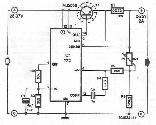
A simple variable power supply circuit can be designed using the LM723 regulator, which provides a maximum current of up to 2A and a variable voltage range between 2 and 25 volts. The LM723 voltage regulator is an integrated circuit...
This figure illustrates a method for generating a momentary 10-kV voltage pulse to initiate plasma discharge across a laser tube. A diode voltage-multiplier circuit is connected in series with the main supply, obtaining its input power from one of...
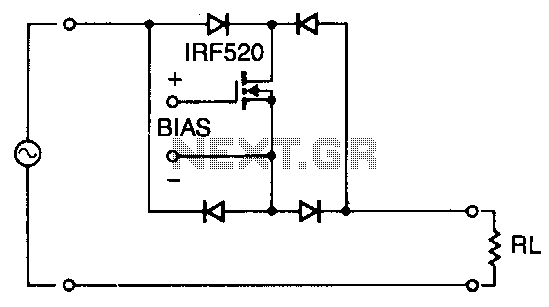
Utilizing four diodes in an array enables the use of a single MOSPOWER transistor for analog switching. The current flow is managed by maintaining the source-base connection of the MOSFET towards the load. It is essential to select diodes...
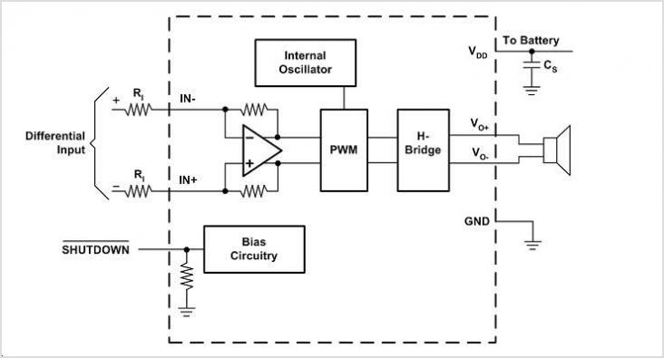
The EUA2123 is a highly efficient Class-D audio power amplifier capable of delivering up to 20W into a 4-ohm load in stereo mode using a single-ended (SE) configuration, or up to 40W into an 8-ohm load in mono mode...
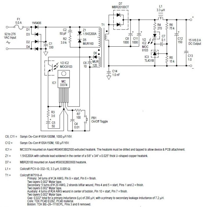
This switching power supply circuit diagram is based on the MC33374 high-power voltage switching regulator IC manufactured by Motorola Semiconductor. The MC33374 switching power supply circuit will provide a maximum output power of around 90 W and requires few...
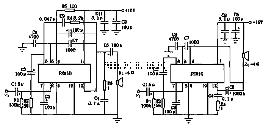
The FS810 circuit serves as a practical implementation of an integrated power amplifier. The FS810 is designed for high-performance use in high-end tape recorders and audio equipment. In the schematic, the speaker is connected to the output capacitor C5...