
MC33374 high power voltage switching regulator
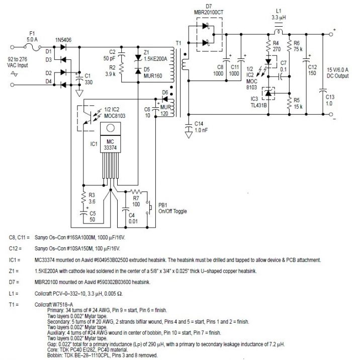
The MC33374 integrated circuit is a versatile high-power voltage regulator designed for use in switching power supply applications. Its architecture allows for efficient conversion of AC voltage to a regulated DC output, making it suitable for a variety of electronic devices that require stable power sources. The circuit typically employs a flyback topology, which is particularly effective for isolating the output from the input and allows for high voltage gain.
In this configuration, the MC33374 can manage input voltages across a wide range, accommodating both fixed and variable AC inputs. The ability to handle up to 150 W under specific conditions makes this circuit particularly valuable for applications demanding higher power outputs. The design simplicity is enhanced by the minimal requirement for external components, which streamlines the manufacturing process and reduces overall system cost.
The transformer, designated as T1 in the circuit, is a critical component that dictates the performance of the power supply. Its design must consider factors such as turns ratio, core material, and winding configuration to ensure efficient energy transfer and minimize losses. While custom transformer designs can be complex, readily available commercial transformers from manufacturers like Coilcraft can provide a viable alternative, ensuring reliability and performance.
Overall, this switching power supply circuit using the MC33374 is a robust solution for applications requiring efficient power conversion, with the flexibility to adapt to various input conditions while maintaining high output power capabilities.This switching power supply circuit diagram is based on the MC33374 high power voltage switching regulator IC manufactured by Motorola Semiconductor. This MC33374 switching power supply circuit will provide a maximum output power around 90 W and require few external components.
The MC33374 switching regulator IC is designed to operate directly f rom a rectified AC line source, and in flyback converter applications are capable of providing an output power in excess of 150 W with a fixed AC input of 100 V, 115 V, or 230 V, and in excess of 90 W with a variable AC input that ranges from 85 V to 265 V. The hard part of these switching power supply circuit is to design the T1 transformer, but you have the design data for that bellow, or you can buy a transformer from Coilcraft.
🔗 External reference
Related Circuits
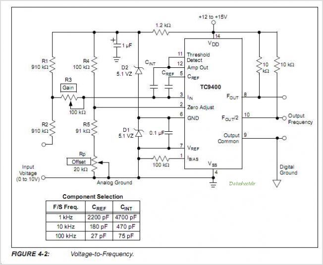
The TC9400, TC9401, and TC9402 are low-cost voltage-to-frequency (V/F) converters that utilize low-power CMOS technology. These converters accept a variable analog input signal and generate an output pulse train, with a frequency that is linearly proportional to the input...
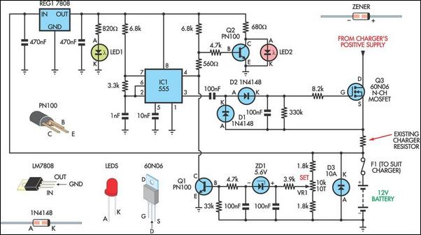
Most commercially available car battery chargers should not be connected to the battery for extended periods, as this can lead to overcharging and subsequent battery damage. This add-on circuit is connected in series with the battery being charged and...
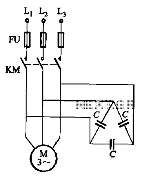
Asynchronous motor reactive power compensation involves directly connecting a capacitor to the stator windings of the asynchronous motor to enhance its power factor. This method is particularly effective for synchronous motors, as it reduces energy consumption related to reactive...
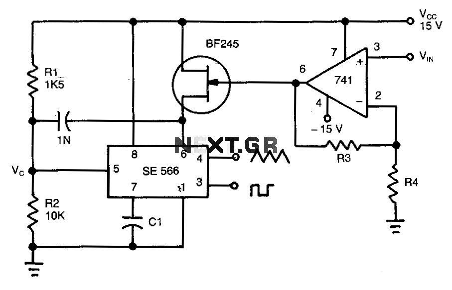
This circuit operates based on the frequency variation of the function generator in relation to the input voltage (ViN). The frequency is influenced by the capacitance and resistor connected to pin 6, with the resistor being substituted by a...
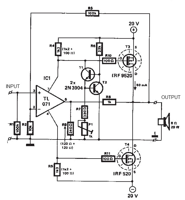
The audio amplifier illustrated in this circuit diagram is a straightforward and efficient audio amplifier circuit based on the TDA1308 integrated class-AB stereo headphone amplifier. This device is manufactured using a 1 mm Complementary Metal Oxide Semiconductor (CMOS) process...
High-efficiency step-down switching regulators for positive voltages are common; however, negative step-down switching regulators (negative voltage in, negative voltage out, common ground) are less well known, despite their frequent necessity. Setting them up is not particularly challenging, but literature...
Warning: include(partials/cookie-banner.php): Failed to open stream: Permission denied in /var/www/html/nextgr/view-circuit.php on line 713
Warning: include(): Failed opening 'partials/cookie-banner.php' for inclusion (include_path='.:/usr/share/php') in /var/www/html/nextgr/view-circuit.php on line 713