
FS810 integrated power amplifier circuit diagram
The FS810 integrated power amplifier circuit is engineered to deliver high-fidelity audio performance, making it suitable for sophisticated audio applications. The circuit’s architecture incorporates various components that enhance audio quality and stability. The feedback path, established by the 100k resistor, is crucial for maintaining linearity and reducing distortion, thereby ensuring a clean amplification of the audio signal.
The Bass Boost network, consisting of the capacitor C (0.047 µF) and resistor R4 (8.2k), is strategically placed to augment the low-frequency response of the amplifier. This enhancement is particularly beneficial for audio playback systems where deep bass reproduction is desired. The selection of component values in this network can be adjusted to tailor the bass response according to specific application requirements.
The bootstrap network formed by C10 and R5 plays a significant role in stabilizing the amplifier's operation by providing the necessary voltage gain and ensuring that the amplifier can drive varying loads effectively. The correction reactance network, composed of R3 and R4, is designed to counteract the inductive effects of the loudspeaker, which can adversely affect the amplifier's frequency response. By minimizing these effects, the circuit achieves improved performance across the audio spectrum.
The dual function of capacitor C5 as both an output coupling capacitor and a part of the impedance bootstrapping network simplifies the circuit design. This design choice reduces component count, which in turn can enhance reliability and reduce manufacturing costs. However, it is essential to ensure that the speaker is properly grounded to maintain circuit integrity and prevent unwanted noise or interference.
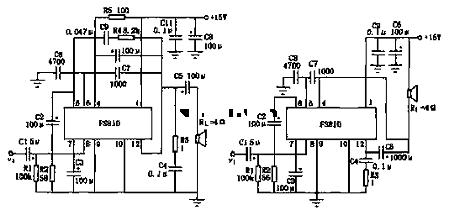
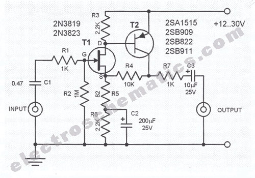
Overall, the FS810 integrated power amplifier circuit exemplifies a well-thought-out design that balances simplicity with high-performance audio capabilities, making it an ideal choice for high-end audio equipment.FS810 practical circuit as shown for the integrated power amplifier. FS810 is a high performance, integrated power amplifier for high-end tape recorders and audio equipment. Fi gure (a), the speaker connected to the output capacitor C5 and the ground, indirect 100k resistor pin and ground constitutes a feedback branch exchange. For the rich bass, plus the C (0.047 F), R4 (8.2k ) branch connected between feet and 12 feet, as Bass Boost network.
C10, R5 bootstrap network, R3, R4 correction reactance network, for eliminating the inductance of the loudspeaker. Figure (b), the positive power supply between the positive electrode and the speaker connected to the output terminal of the capacitor C5, the output capacitor C5 and doubles as a speaker impedance bootstrapping network element, thus less components, the circuit is simple, but the speaker must be suspended grounded.
Related Circuits
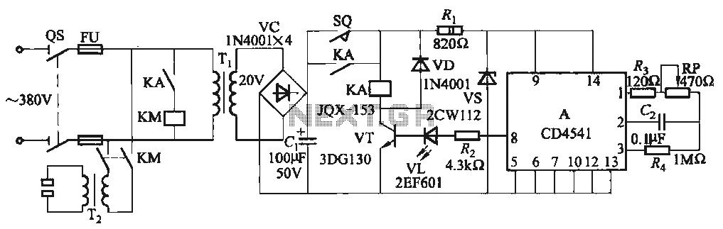
One Foot Spot Welder circuit. The circuit utilizes the IC CD4541 to provide precise delay characteristics, enabling the electrical time constant necessary for effective welding. This ensures consistent welding quality across identical weldments. For varying weldments, the electrical locator...
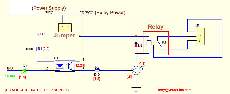
Controlling higher-power devices such as lights, motors, pumps, and doors with an Arduino can be both fascinating and practical. However, managing power line voltages presents challenges and potential hazards. There are essential differences between controlling AC and DC power,...
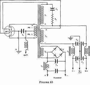
The more one understands about any subject, the more interesting it becomes. As this article is read, it will be found that the subject of... A comprehensive electronic schematic typically involves various components, each serving a specific function in the...
This microphone preamplifier utilizes the low-noise integrated circuit uA739. The circuit serves as an example of an effective preamplifier design for dynamic microphones. The integrated circuit contains two identical preamplifier circuits, with the second preamp functioning in the same...
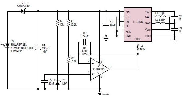
A simple supercapacitor charger electronic project can be designed using the LTC3625 integrated circuit (IC) from Linear Technology. This circuit is capable of charging two supercapacitors in series to a fixed output voltage of either 4.8V/5.3V or 4V/4.5V, which...
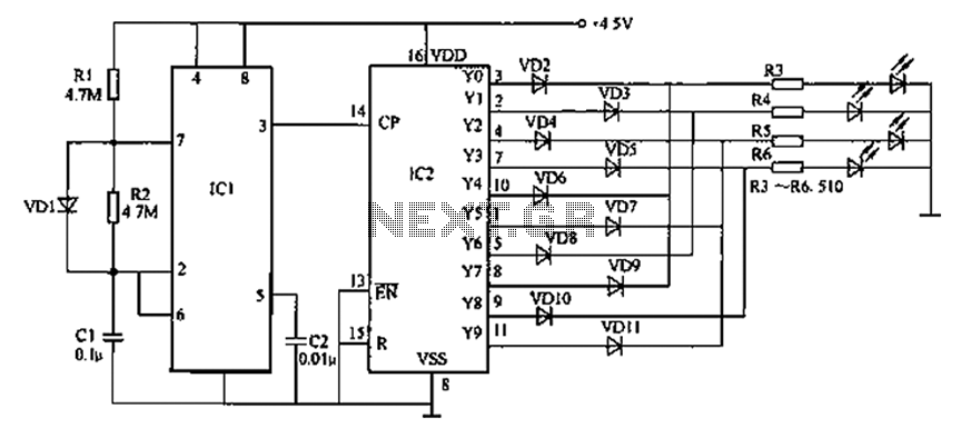
Prolonged reading or writing, maintaining a close distance between the eyes and the book, and insufficient lighting are primary contributors to decreased vision. This example describes a visual fatigue eliminator designed to alleviate eye fatigue and prevent myopia. The...