
Compact and easy joule ringer circuit

To implement a circuit that converts 12V to 120V using a joule ringer, a careful selection of components is essential. The core of this design involves an EI transformer, which is characterized by its laminated iron core that minimizes energy losses. The air core variant can also be employed for specific applications where weight and size are critical factors, though it may have lower efficiency compared to its iron core counterparts.
The circuit typically operates by utilizing a joule ringer topology, which is a type of resonant converter. This configuration allows for the efficient transfer of energy from the input voltage to a higher output voltage. The primary winding of the transformer is connected to the input voltage, while the secondary winding is designed to output a significantly higher voltage, in this case, 120V.
To achieve the desired voltage conversion with a low input voltage of 1.5V or 3V from two NiCd batteries, the circuit may include a switching mechanism, such as a transistor, to rapidly turn the current on and off. This switching action generates a high-frequency oscillation, which is crucial for the transformer to step up the voltage effectively. The use of capacitors in the circuit can further enhance the energy transfer and stabilize the output voltage.
It is important to incorporate protective components, such as diodes and fuses, to safeguard the circuit against overvoltage and current surges. Additionally, proper heat dissipation measures should be implemented, as transformers can generate heat during operation, especially at higher output levels.
This configuration allows for the practical application of low-voltage power sources to achieve high-voltage outputs, making it suitable for various applications where compact and efficient power conversion is required.I have followed some threads on ringer and have seen many variants, specially the transformer used like aircore and stepdown transformer types. Some similar circuits : 1)12V-to-120V joule ringer,uses 12v EI transformer: exists(peanut butter model) we want to power with 1.5 or 3V,limiting to 2 nicd 🔗 External reference
Related Circuits
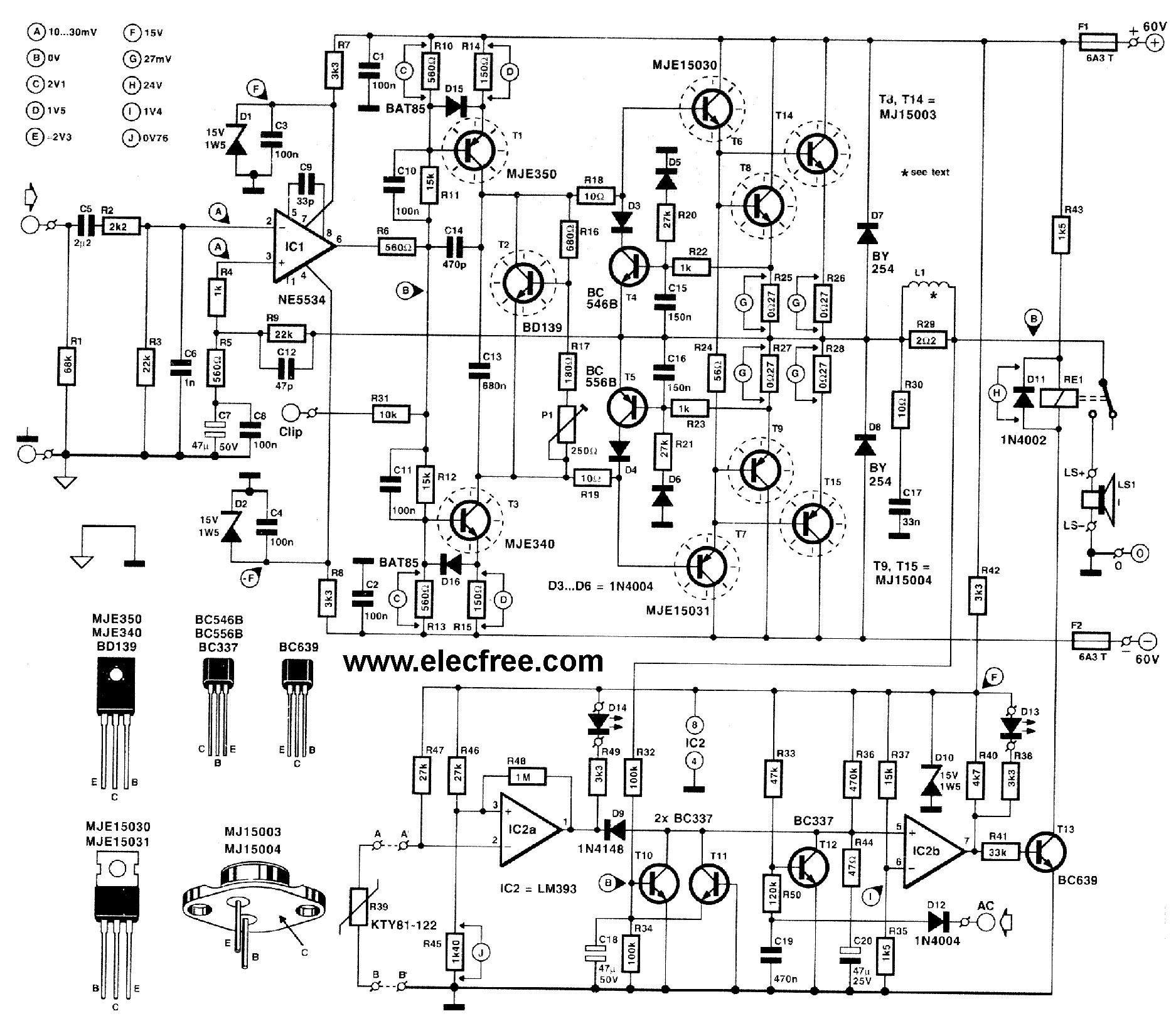
This circuit is designed for friends who are interested in high-power amplifier circuits. It can deliver approximately 300 Watts RMS and operates as an OCL (Output Capacitor-Less) Class AB amplifier, providing high sound power while systematically protecting the loudspeaker...
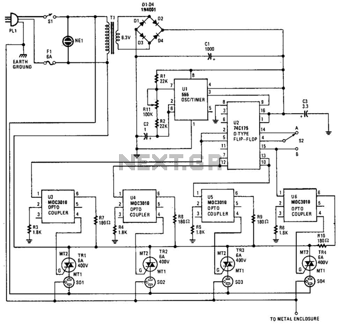
The integrated circuit U1 (a 555 oscillator/timer) is configured as a conventional pulse generator. The frequency of the pulse generator is adjusted using potentiometer R11. Resistor R2 limits the maximum frequency attainable. The output from the pulse generator is...
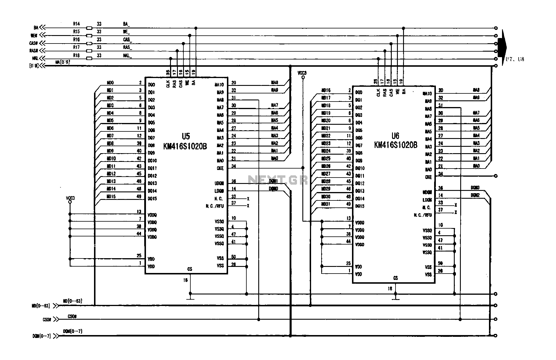
A digital signal processing circuit that operates in conjunction with a memory system for temporarily storing image data. The DPTVT-3D/MV digital processing chip requires four KM416S102 memory units, each providing 16 MB of digital memory. The circuit structure is...
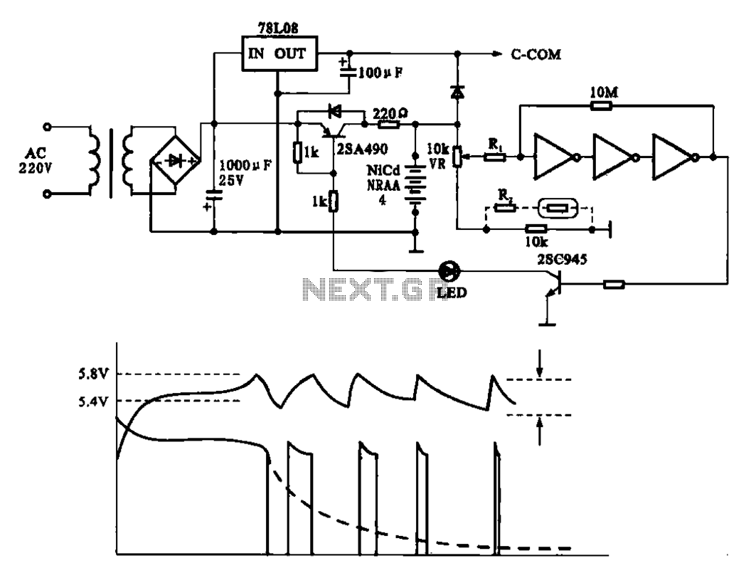
Fast charging circuit that illustrates voltage and current waveforms along with the configuration of the fast charge circuit for the charger. The detection and control circuit consists of three inverters (GMOS) from integrated circuits, enabling automatic control functions. The fast...
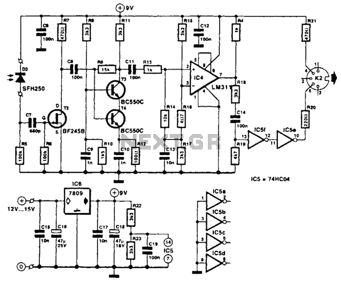
The receiver photodiode SFH250 is utilized to convert optical data pulses at a rate of 32.5 Kbps into electrical signals. The buffer T2 transmits these signals to a cascade amplifier consisting of transistors T3 and T4, followed by an...
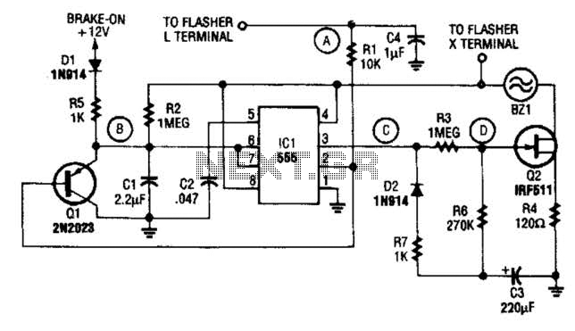
The STS schematic illustrates a circuit designed to alert a driver when the turn signal has been active for more than 15 seconds. The voltage at the gate of transistor Q2 increases in response to the charge accumulated on...