
keytop and display for electronic devices
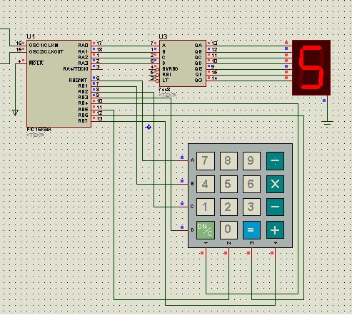
The keyboard key mechanism typically employs a simple yet effective design that includes a keycap, a switch, and a circuit board. The keycap is the visible part of the key that the user interacts with, while the switch is the component that closes the circuit when the key is pressed. The circuit board contains conductive traces that facilitate the electrical connection when the switch is activated.
When a key is pressed, the keycap moves downward, compressing a spring or a membrane beneath it. This action causes the switch to close, allowing current to flow through the circuit traces on the circuit board. The closed circuit sends a signal to the computer or device, indicating which key has been pressed. Upon release, the spring or membrane returns the keycap to its original position, opening the circuit and stopping the current flow.
In addition to mechanical switches, some keyboards utilize membrane technology, where the contacts are made from flexible printed circuits. These designs offer a lower profile and can be more cost-effective, though they may not provide the same tactile feedback as mechanical switches.
The reliability and responsiveness of keyboard keys have made them a staple in user interface design across various devices, from computers to gaming consoles, and even in mobile devices. The evolution of keyboard technology continues to influence user experience and ergonomic design in modern electronics.A keyboard key figure who work with electrical contact between the surface of the keyboard and the underlying circuit when pressed keytop area, used by some home computers the early 1980s, and has been widely used in consumer electronic devices. 🔗 External reference
Related Circuits
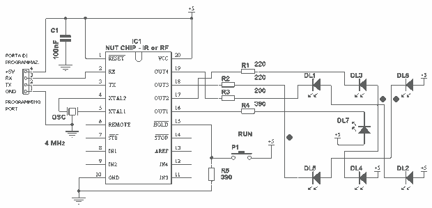
This project takes advantage from -HOLD input, which is connected to push-button P1. As long as the -HOLD input is low, truth table's timeouts have no effect because this input serves to disable any state change provoked by timers....
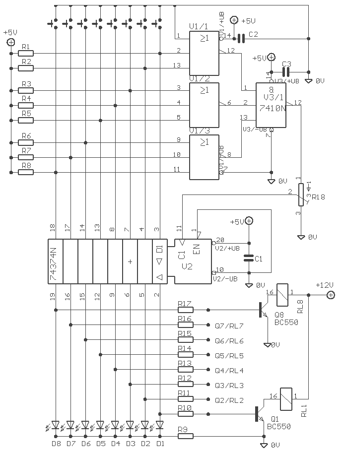
The Elect. Sel. 8 is a simple circuit, with a choice of 8 sources of any sort, of 8 independent switches. Each switch corresponding with a relay for example the switch S1 activates the RL1 etc. The uses of...

The following circuit illustrates the iButton Electronic Lock Schematic diagram. This circuit is based on the Atmel AT89C2051 integrated circuit (IC). Features include an onboard power supply comprising a transformer (T1) and a voltage regulator (U4), a bridge rectifier...

The simplicity of a traditional die makes it exceptionally difficult to create a fully equivalent electronic version, primarily because an electronic version requires a power supply and a collection of electronic components that occupy a significantly larger volume than...
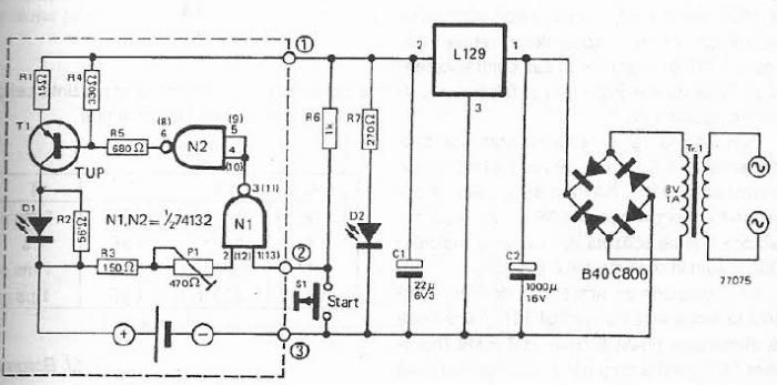
The maximum charge voltage is set at 1.45 volts, while the higher trigger threshold is approximately 1.7 volts. This voltage can be adjusted using potentiometer P1 to reach 1.45 volts. A TTL control signal is output by the voltage...

The 4Y4 is a monolithic liquid crystal display rangefinder circuit. The instrument comprises an ultrasonic transmitter, a receiver, an LCD display, buttons, switches, and a buzzer (or speaker). To simplify wiring, the 4Y4 is directly welded to the back...
Warning: include(partials/cookie-banner.php): Failed to open stream: Permission denied in /var/www/html/nextgr/view-circuit.php on line 713
Warning: include(): Failed opening 'partials/cookie-banner.php' for inclusion (include_path='.:/usr/share/php') in /var/www/html/nextgr/view-circuit.php on line 713