
140W amateur radio linear amplifier 2-30Mhz
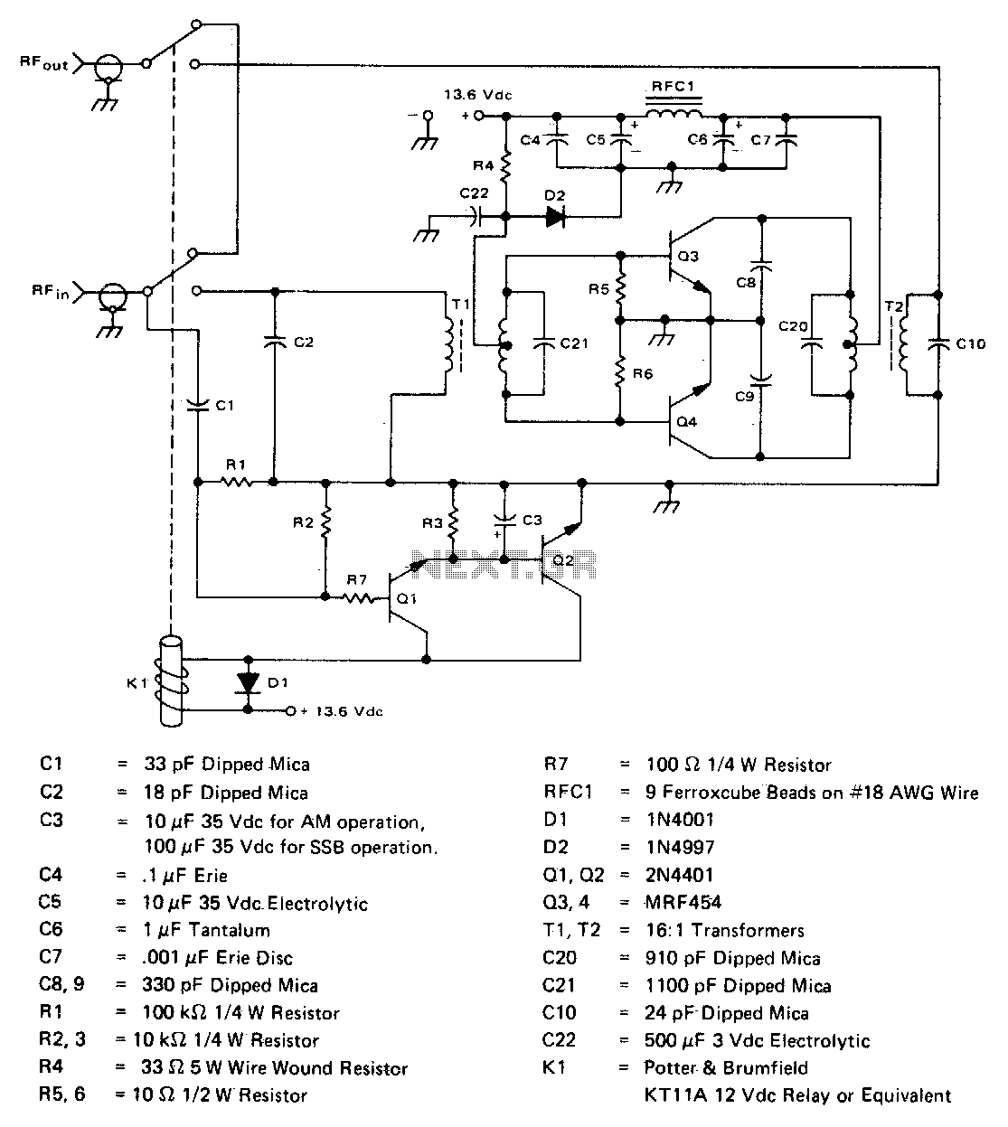
The amplifier circuit is designed to efficiently amplify RF signals, making it suitable for various applications, including communication systems and signal processing. The MRF454 devices are known for their high efficiency and reliability, which contributes to the overall performance of the amplifier.
The design typically includes a few critical components: the two MRF454 transistors, biasing resistors, coupling capacitors, and a power supply decoupling network. The transistors are arranged in a push-pull configuration to maximize power output and improve linearity. The input drive of 5 W is fed into the base of the transistors through coupling capacitors, which block DC voltage while allowing AC signals to pass.
The output stage of the amplifier is designed to deliver 80 W of power, ensuring that the amplified signal maintains fidelity and strength. The circuit should also incorporate adequate heat sinking for the MRF454 devices to manage thermal dissipation effectively during operation.
Power supply considerations are crucial; a stable 12 V DC source is necessary to ensure consistent performance. Additional bypass capacitors may be included near the power supply connections to filter out any noise and provide a stable voltage to the amplifier during operation.
Overall, this amplifier circuit is a practical solution for those needing a cost-effective and efficient amplification system, leveraging the capabilities of the MRF454 transistors to achieve the desired performance specifications.This inexpensive, easy to construct amplifier uses two MRF454 devices Specified at 80 W power output with 5 W of input drive, 30 MHz, ana 12 Vdc. 🔗 External reference
Related Circuits
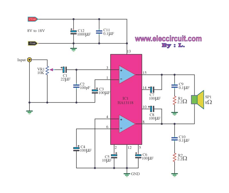
The amplifier circuit utilizes the HA13118 IC, a Hitachi component designed to deliver 18 watts of output power. This integrated circuit operates as a Class AB amplifier. The HA13118 IC is a versatile audio amplifier designed for high-fidelity applications, providing...
This amplifier is designed for outdoor installation and is connected to an indoor power line box. It utilizes either 50-ohm or 75-ohm coaxial cables for the connection between indoor and outdoor units. The amplifier circuit board is depicted in...
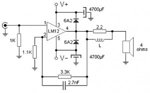
Almost all audio power amplifiers utilize integrated circuit amplifiers, such as the M12CLK, which is a power operational amplifier. This amplifier allows for an output stage that operates at an impedance of 2 ohms and provides a power gain...
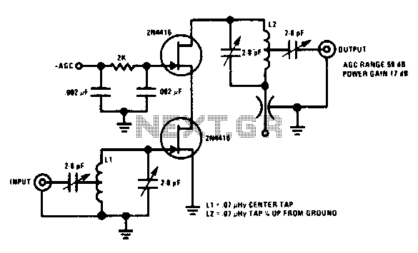
This 200 MHz JFET cascode circuit features low cross-modulation, large signal handling ability, no neutralization, and automatic gain control (AGC) managed by biasing the upper cascode JFET. The only special requirement of this circuit is that the drain-source saturation...
This is a good example preamplifier for microphones that can be used in mixing consoles. The circuit uses a dual op-amp, type NE 5532. The amplifier must be adjusted. This connect the power supply and control over P1 such...
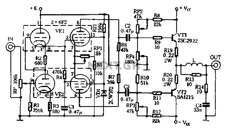
The pre-amplifier stage consists of an inverter made up of two 6F2 pentodes, with pin configurations illustrated in Figure 2.9. The electrical parameters are detailed in Table 2-3. The 6F2 tubes are well-regarded for their intensity and resolving power,...