
A simple and effective short-wave antenna amplifier circuit

This outdoor amplifier is engineered to enhance signal strength for applications requiring reliable performance in outdoor environments. The use of coaxial cables with 50-ohm or 75-ohm impedance ensures compatibility with various transmission lines, optimizing signal integrity. The main circuit board's compact size (6.4 cm x 2.4 cm) allows for efficient integration into a range of enclosures, while the power supply box, measuring 5.1 cm, is designed to accommodate the necessary voltage and current specifications for the amplifier's operation.
In terms of component selection, the use of a 1 µH inductor (L1) is critical for the circuit's functionality, as it helps to filter and stabilize the signal. The precise resistance and capacitance values are essential for tuning the circuit to the desired frequency range, ensuring that the amplifier operates effectively within its intended parameters. The choice of a low-noise transistor enhances the amplifier’s performance by minimizing signal degradation, which is particularly important in high-frequency applications.
The winding of L2 with 300 turns of wire of the same diameter as L1 ensures consistent inductance characteristics, which are vital for maintaining signal quality. The inclusion of diodes D1 and D2 not only serves as indicators but also stabilizes the voltage levels within the circuit, preventing fluctuations that could lead to performance issues.
The integration of a 100 mA fuse adds a layer of protection to the circuit, safeguarding against overcurrent conditions that could potentially damage the components. This design consideration is crucial for outdoor applications where environmental factors could lead to unexpected electrical challenges.
Overall, this amplifier circuit is a robust solution for outdoor installations, combining thoughtful design with high-quality components to deliver reliable performance in demanding conditions.This amplifier is the outdoor type, line installed outdoors, the amp`s main line; Figure 2 is the indoor power line box. Indoor and outdoor use between 50 ohm or 75 ohm coaxial cable to connect. e› 3 Figure 3, Figure 4 is the amplifier circuit board, and Figure 3 is the main circuit board, the actual size is 6.
4 cm G— 2. 4 cm Figure 4 is a circuit board power supply box, the actual size of 5. 1 cm. Good circuit board in Figure After processing, followed by selecting components, circuit in Figure 1, L1 with the color code 1uH inductance, resistance and capacitance values selected according to the diagram, transistor low noise high quality ultra-high-frequency control, in addition to the figure of 9018, you can also use 9016, 1359 and so on, L2 winding with waste in the week, the week of the original wire diameter with the same number of laps for the 300 laps, D1, D2 is light, but also for regulators to use. Figure 2 circuit in Figure 1 in the L1 with the L2 as the production, use 100mA fuse on it, with the other components are the same as in Figure 1, click the image selection.
🔗 External reference
Related Circuits
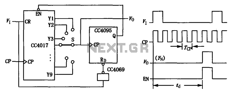
CC4017 counter/distributor featuring a circuit diagram of the delay. The CC4017 is a decade counter and distributor that counts from 0 to 10, providing ten output states. It is commonly used in various digital applications for counting purposes, such as...
The circuit diagram is designed to enhance the input of a telescopic whip antenna. The preamplifier is intended to operate within the medium waveband, covering frequencies from approximately 550 kHz to 1650 kHz. A tuning voltage is provided through...
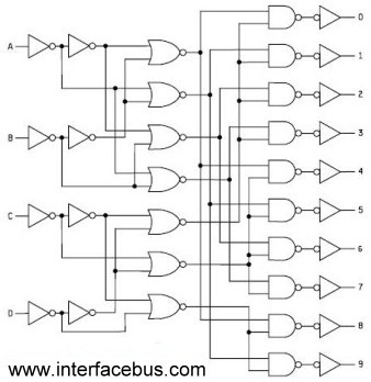
Binary Coded Decimal (BCD) is a number system that counts from 0 to 9 and then repeats. The table below illustrates the conversion between different numbering systems and BCD code. BCD is also known as 8421 because the least...
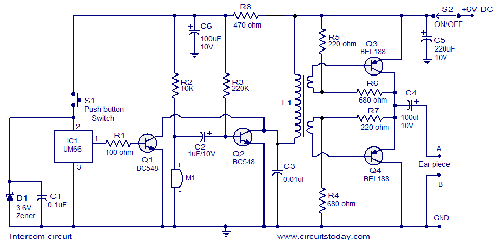
A straightforward intercom circuit designed using transistors. It does not require a changeover switch and can be used similarly to a telephone. This intercom circuit utilizes transistors to facilitate communication between two or more stations without the need for complex...
A sine wave oscillator can be implemented using a Wien-Bridge oscillator, similar to the previous sine wave oscillator circuit; however, another method is now presented. The Wien-Bridge oscillator is a type of electronic oscillator that generates sine waves. It is...
This page outlines the development of electronics for displaying a monochrome video image on an electrostatic oscilloscope tube. This work complements the Electron Optics section in the Experiments category. The primary objective is to showcase a moving video image...