
Microphone Preamplifier with 5532 NE
The described circuit is a preamplifier designed specifically for microphone applications, suitable for integration into mixing consoles. The core component of this circuit is the NE5532, which is a low-noise, dual operational amplifier. This device is favored for its high performance, including low distortion and wide bandwidth, making it ideal for audio applications.
The circuit configuration begins with the power supply connection. It is essential to ensure that the NE5532 is powered appropriately, typically using a dual power supply configuration (e.g., ±15 V). The adjustment of the amplifier is facilitated through variable resistors P1 and P2. P1 is set to achieve half the supply voltage (6 V) at pin 3 of the NE5532, which is crucial for proper biasing of the op-amp and ensures optimal performance. This is done by connecting P1 in a voltage divider configuration.
P2 is a potentiometer that allows for volume control. By adjusting P2, the output level can be modified according to the user’s preference. This feature is particularly useful in live sound applications where real-time adjustments to audio levels are necessary.
The circuit's passive components include various resistors and capacitors, which play critical roles in shaping the frequency response and stability of the amplifier. The resistors R1, R2, R4, R5, and R6 are chosen to set the gain and input impedance of the amplifier. R1, with a value of 8.2 kOhm, serves as the input resistor, while the others (10 kOhm each) help in feedback and gain setting.
Capacitors C1, C2, C4, and C6 (10 µF) are used for coupling and decoupling, ensuring that DC bias levels do not affect audio signals. C3 (470 nF) and C5 (100 nF) are likely used for filtering purposes, helping to eliminate high-frequency noise and stabilize the power supply lines.
In summary, this preamplifier circuit effectively amplifies microphone signals while allowing for user-friendly volume adjustments. Its design leverages the performance characteristics of the NE5532 op-amp, complemented by a well-selected array of passive components to ensure high fidelity and reliability in audio applications.This is a good example preamplifier for microphones that can be used in mixing consoles. The circuit uses a dual op-amp, type NE 5532. The amplifier must be adjusted. This connect the power supply and control over P1 such that half the supply voltage (6 V) on pin 3 of IC1 is. P2 is then adjusted to the desired volume. Parts List R1 = 8.2 kOhm R2, R4, R5, R6 = 10 kOhm R3 = 1 kOhm P1 = 4.7 kOhm P2 = 100 kOhm C1, C2, C4, C6 = 10 uF C3 = 470 nF C5 = 100 nF IC1 = 5532 NE 🔗 External reference
Related Circuits
This circuit diagram illustrates the conversion of a speaker into a microphone. When sound waves impact the diaphragm of a speaker, fluctuations occur in the coil, generating an induced voltage. This induced voltage is typically substantial but low in...
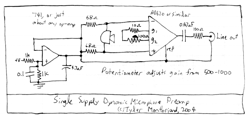
This circuit amplifies the output from a 150-ohm dynamic microphone to line level using an instrumentation amplifier. Instrumentation amplifiers are similar to operational amplifiers (op-amps) but offer adjustable gain and improved common-mode rejection. They provide high gain, high precision,...
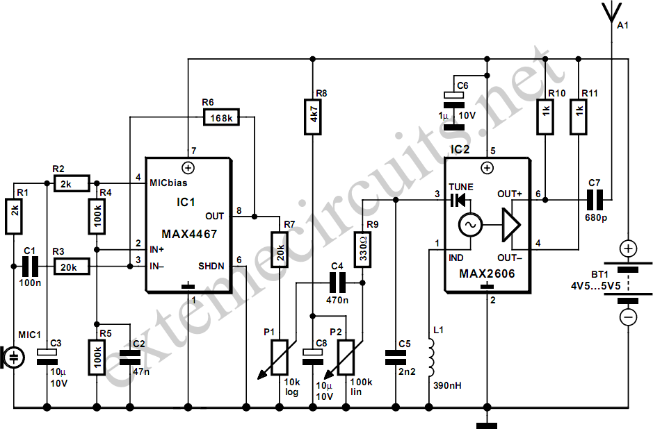
This project involves a simple and cost-effective transmitter designed for hobbyists and home experimenters, capable of transmitting speech over a short distance. It functions as a cordless microphone, utilizing two integrated circuits from Maxim. The first IC, MAX4467, acts...
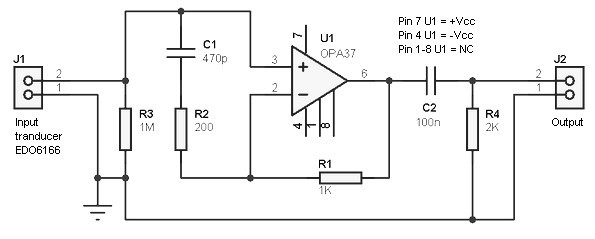
Hydrophone preamplifier circuit. It is simple and utilizes only conventional components. The transducer used is of the piezo type and has a relatively high output impedance, necessitating a preamplifier with a high input impedance. The hydrophone preamplifier circuit is designed...
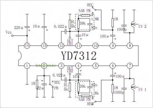
The YD9088 is a bipolar integrated circuit designed for use in mono portable and pocket radios. It is advantageous when minimizing peripheral components, which should be of small dimensions and low cost, is a priority. The circuit incorporates a...
This circuit was submitted by Graham Maynard from Newtownabbey, Northern Ireland. It has an exceptionally fast high-frequency response, as demonstrated by applying a 100kHz square wave to the input. All graphs were produced using Tina Pro. The circuit in question...