
1500W Power Amplifier

The 1500W power amplifier circuit is designed for high-performance audio applications, providing significant power output while maintaining fidelity. The use of 10 pairs of power transistors allows for efficient heat dissipation and enhanced current handling capabilities, which are crucial for achieving the desired output power without distortion.
The circuit typically includes a differential input stage that amplifies the input audio signal. This stage is followed by a voltage gain stage, which may utilize additional transistors for further amplification. The output stage consists of the aforementioned power transistors configured in a push-pull arrangement, ensuring that both halves of the audio waveform are amplified effectively.
To manage thermal performance, the circuit design incorporates adequate heat sinking for the power transistors. This is essential to prevent thermal runaway, which can lead to component failure. Biasing circuits are also included to maintain the transistors in their optimal operating range, ensuring linear amplification and minimizing crossover distortion.
Feedback mechanisms are often employed in the design to stabilize gain and improve linearity. Capacitors and resistors are strategically placed throughout the circuit to filter noise and stabilize the power supply, which is critical for high-power applications.
Overall, this power amplifier circuit is suitable for driving large speakers or subwoofers in professional audio systems, providing the necessary power and clarity for high-volume sound reproduction. Proper design considerations, such as layout and component selection, are vital for achieving the best performance and reliability.1500W power amplifier circuit design diagram by Rod Elliott. The circuit is built using 10 pairs of power transistor MJ15024 and MJ15025 (or MJ21193/MJ21194) 🔗 External reference
Related Circuits
This is the voltage converter to get the voltage of ±1.25-30V from the input voltage of ±35V. I am using the 3 terminal voltage regulator for the voltage to be changed in this unit. As the regulator, LM317 is...
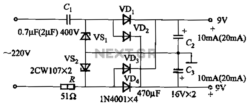
The circuit's output current capacity is influenced by the bulk capacitor Cl. When the capacitance of Cl is changed from 0.7 µF to 2 pF, the output current can be increased from approximately 10 mA to around 20 mA,...
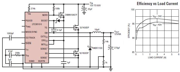
The LTC3810-5 synchronous step-down switching regulator controller allows for the design of a straightforward 12-volt switching power supply electronic project with minimal external components. This controller can directly reduce voltages from up to 60V, making it suitable for telecommunications...
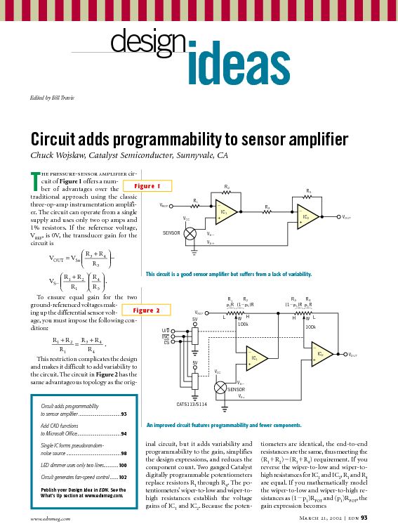
This tutorial provides information related to sensor amplifiers, schematics, and noise. It presents a discussion around sensors and their outputs. Sensor amplifiers are critical components in various electronic systems, especially in applications where signals from sensors need to be conditioned...
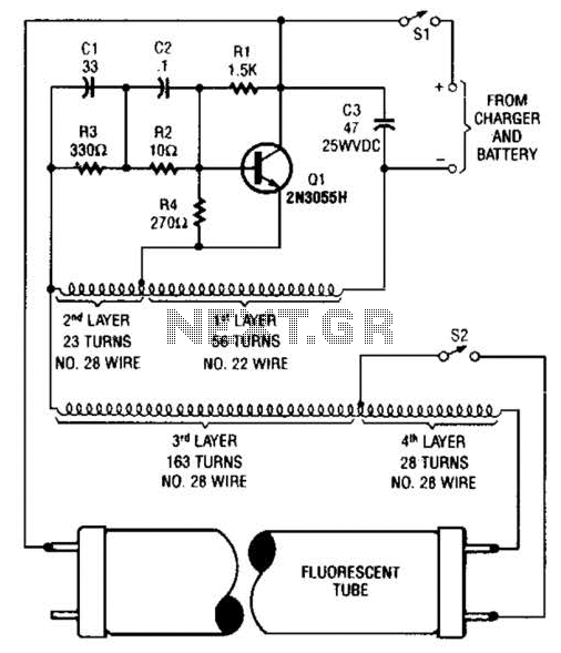
A 2N3055 oscillator (Q1) drives a homemade transformer, wound on a Vk ferrite rod. S2 is used as a filament switch and can be eliminated if desired. A 20-W fluorescent tube is recommended. The supply voltage is 12 V. The...
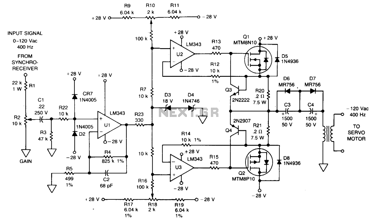
The signal from a synchro receiver or a variable resistive cam follower (potentiometer) is amplified by operational amplifier U1, with its output swing constrained by back-to-back Zener diodes D3 and D4. This amplified signal is then fed into operational...