
Tutorial Sensor Amplifier
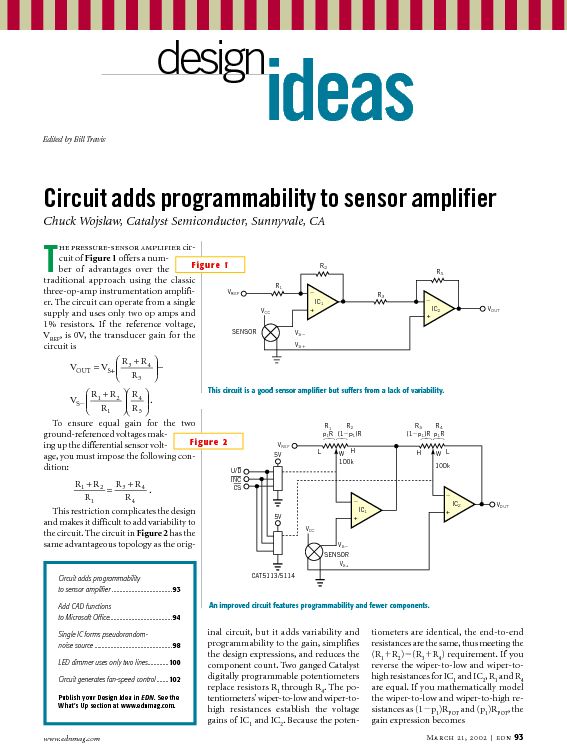
Sensor amplifiers are critical components in various electronic systems, especially in applications where signals from sensors need to be conditioned before further processing. A sensor amplifier typically amplifies the small signals generated by sensors, which can be affected by various forms of noise. The schematic of a sensor amplifier circuit generally includes the sensor itself, an operational amplifier (op-amp), resistors for gain setting, and capacitors for noise filtering.
In a typical configuration, the sensor generates a voltage signal proportional to the physical quantity being measured, such as temperature, light, or pressure. This signal is often too weak to be processed directly by subsequent circuitry, necessitating amplification. The op-amp is used to increase the signal level while maintaining linearity. Feedback resistors are utilized to set the gain of the amplifier, allowing for customization based on the sensor's output characteristics and the requirements of the following stages.
Noise is an important consideration in the design of sensor amplifier circuits. Various types of noise, such as thermal noise, flicker noise, and electromagnetic interference, can adversely affect the signal integrity. To mitigate these effects, careful layout design, proper grounding techniques, and the use of filtering capacitors are essential. The placement of components in the schematic should minimize the length of signal paths and reduce the potential for noise pickup.
In summary, the design of a sensor amplifier circuit involves a thorough understanding of the sensor characteristics, op-amp configurations, gain setting, and noise management strategies to ensure accurate and reliable signal processing.In this tutorial we can get information related to sensor amplifier, schematic, and noise. This tutorial presents discussion around sensor, output, and.. 🔗 External reference
Related Circuits
Amplifying weak radio signals presents the challenge of also amplifying noise. The ability to receive signals is contingent on the level of background noise, which can include man-made interference or static. In this design, the RF signal first encounters...
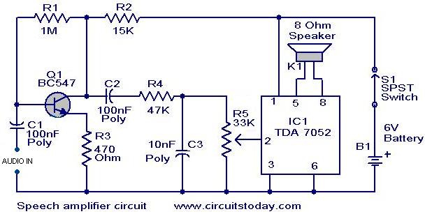
This circuit can be housed within a box containing a speaker to create a convenient microphone amplifier. It is suitable for use by teachers, guides, lecturers, and others in crowded or noisy environments. The design is based on the...
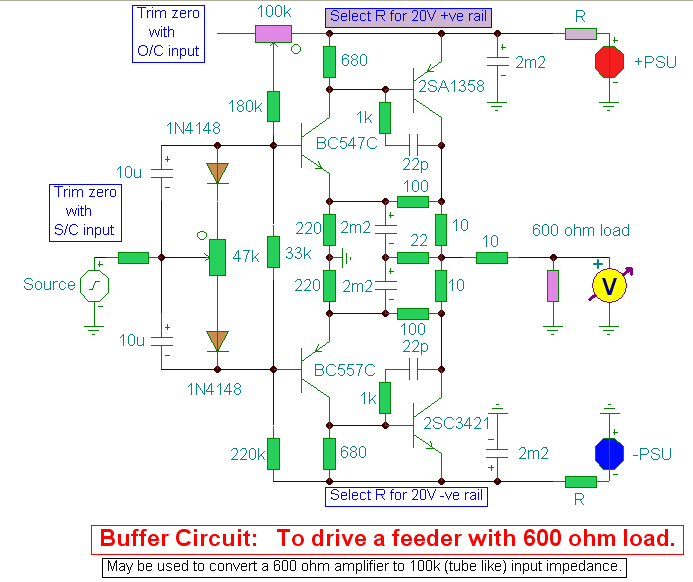
A hi-fi preamplifier designed to convert high output impedance amplifiers to 600-ohm outputs. The described hi-fi preamplifier is engineered to facilitate the interfacing of high output impedance audio sources with low impedance loads, specifically targeting a standard output impedance of...
This circuit consists of an infrared phototransistor and an infrared LED. The transducer operates on the principle of light reflection, specifically infrared light. The skin serves as a reflective surface for the infrared light, and the density of blood...
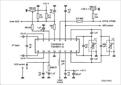
The TDA9813T is an integrated circuit designed for processing vision intermediate frequency (IF) signals and dual frequency modulation (FM) demodulation of sound. It operates with a single reference QSS-IF in television (TV) and video cassette recorder (VCR) applications, specifically...
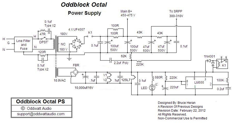
One of the advantages of hosting a hobby website is the opportunity to connect with individuals via email who share similar interests. Since posting Bruce's initial OddWatt project on the site, communication has occurred with numerous DIY hobbyists who...
Warning: include(partials/cookie-banner.php): Failed to open stream: Permission denied in /var/www/html/nextgr/view-circuit.php on line 713
Warning: include(): Failed opening 'partials/cookie-banner.php' for inclusion (include_path='.:/usr/share/php') in /var/www/html/nextgr/view-circuit.php on line 713