
15V Simple FM Transmitter
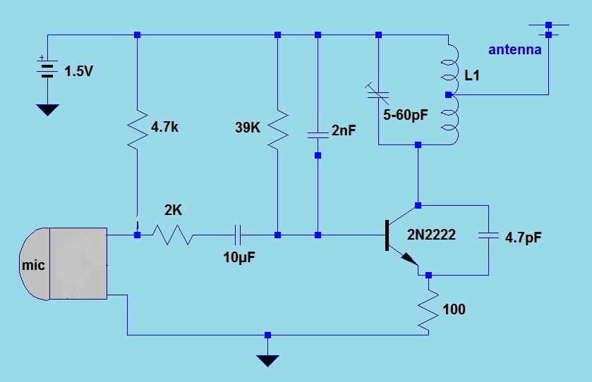
This FM transmitter circuit is designed for simplicity and efficiency, making it suitable for educational purposes or hobbyist projects. The power supply of 1.5V is sufficient to drive the circuit and allows for portability. The LC resonant circuit, composed of the inductor L1 and the capacitor, is crucial in determining the operating frequency of the transmitter. The specified frequency range of 80 to 110 MHz is typical for FM broadcasting, allowing compatibility with standard FM receivers.
The inductor L1, constructed with 8 turns of No. 22 wire, serves as the primary element in the resonant circuit. The choice of wire gauge and the number of turns directly affect the inductance value, which must be calculated to ensure proper tuning of the circuit to the desired frequency. The physical dimensions of the inductor, with a diameter of 4 to 5 cm, are practical for maintaining a compact design while providing adequate inductance.
The antenna, a 6-inch cable, is connected to the copper half of the inductor, playing a vital role in radiating the modulated signal. The length of the antenna is a critical factor, as it influences the transmission range and efficiency of the signal. The use of a simple cable as an antenna makes the circuit easy to assemble and test.
Regarding component selection, the circuit allows for flexibility in the choice of resistors and capacitors, enabling users to replace components with those of similar values without significantly affecting performance. The 1/4 watt ceramic resistor is suitable for this low-power application, while the 10µF electrolytic capacitor ensures stable operation of the circuit. The inclusion of a variable capacitor (5-60pF) provides the ability to fine-tune the frequency, allowing for adjustments based on the specific requirements of the transmission environment.
Overall, this FM transmitter circuit represents a straightforward approach to frequency modulation, emphasizing ease of construction and adaptability in component selection. Such a design is beneficial for those interested in exploring radio frequency transmission and modulation principles.This simple FM (frequency modulation) transmitter is powered only by a 1. 5V battery and uses only one frequency of this transmitter transistor. The is controlled by the LC resonant circuit and operates from 80 to 110 MHz The inductor L1 is 8 turns of wire wound magnetic No. 22 with diameter of 4 to 5 cm or the diameter of a pencil. The antenna is a 6-inch cable connected to the copper half of the L1 inductor. Other parts are not critical and can be replaced by their nearest value. Resistance 1 / 4 watt ceramic capacitor type and, except for electrolytic capacitor 10uF. 5-60pF capacitor is a type of court or variable rate. 🔗 External reference
Related Circuits
This circuit is utilized for proximity detection and touch-controlled switching. When a finger approaches the sensor, it generates a capacitance to ground with a value ranging from 30 to 100 pF. Components involved include a resistor, capacitor, diode, and...
The typical BPM range for music is between 40 and 240 BPM, corresponding to periods of 1500 ms and 200 ms, respectively. A BPM of 120 equates to a period of 500 ms. The circuit requires a resistor R4...
A 1.5 Volt tracking transmitter utilizing simple circuits. The current draw for this tracker is 3.7 mA, allowing the 1.5V button cell to have a prolonged lifespan. The 1.5 Volt tracking transmitter is designed to operate efficiently with a low...

In typical push-pull driver applications, the NPN-PNP transistor pair is alternately activated and deactivated using a square-wave signal. A basic driver circuit employs an inverter between the V1 and V2 inputs to toggle the output transistors. However, mismatched turn-on...
A functional AM transmitter has been completed, primarily based on Phil's Li'l 7 Transmitter design. Achieving oscillation in LC-based transmitters can be challenging without the correct combination of tubes and coils. This transmitter utilizes a 6J5 and a 6SA7...
This transmitter operates on a 9-V battery and can function as a wireless microphone compatible with standard 88- to 108-MHz FM broadcast receivers. To adhere to FCC regulations, the antenna length should not exceed 12 inches. The inductor L1...