
1.5 Volt Tracking Transmitter
The 1.5 Volt tracking transmitter is designed to operate efficiently with a low current draw of 3.7 mA. This low power consumption enables the use of a 1.5V button cell battery, which can provide extended operational time before requiring replacement. The circuit typically comprises a transmitter module, a power supply section, and an antenna for signal emission.
The transmitter module may include a microcontroller or an oscillator circuit that generates a specific frequency signal. The simplicity of the circuit allows for easy assembly and troubleshooting, making it suitable for various applications such as personal tracking devices or remote monitoring systems.
The power supply section is designed to regulate the voltage from the button cell to ensure stable operation of the transmitter. This may include components such as capacitors for filtering and resistors for current limiting. The antenna, which can be a simple wire or a more complex design, is essential for transmitting the signal over a desired distance.
Overall, this tracking transmitter circuit exemplifies a straightforward approach to creating a low-power, efficient device capable of reliable performance in tracking applications.1.5 Volt Tracking Transmitter, Simple circuits , The current draw for this tracker is 3.7mA, so the 1.5V button cell will last awhile. What the heck am I suppose to hear you ask? When your circuit is.. 🔗 External reference
Related Circuits
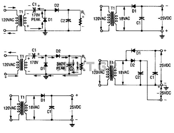
During the first half-cycle, Diode D1 conducts while Diode D2 is in the off state. Capacitor C1 charges to a peak voltage of 170 V, and Capacitor C2 discharges through the load resistor RL. In the second half-cycle, the...
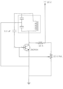
The frequency remains stable as the voltage decreases. It is referred to as the "backwards JT" because it operates optimally with a bifilar coil and a single transistor. With a modification to the circuit, it is possible to deplete...
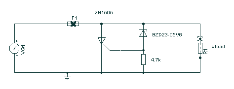
Safety devices like fuses provide protection against excess current, but do nothing for transients and short duration spikes of high voltage on the power supply lines. This circuit uses the "crowbar" method and provides fast protection against transient voltage...
Figure 99-1(a)'s circuit exhibits a high output impedance due to the small effective capacitance of the series-connected capacitors, resulting in considerable voltage loss from the diode drops. This circuit requires two diodes and two capacitors to generate a DC...
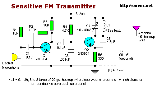
Sensitive FM Transmitter. Additional Notes: The default for the capacitors type is ceramic, preferably the NPO 1% type or equivalent. However, nothing critical is here; any type can be used. The sensitive FM transmitter circuit is designed to operate in...
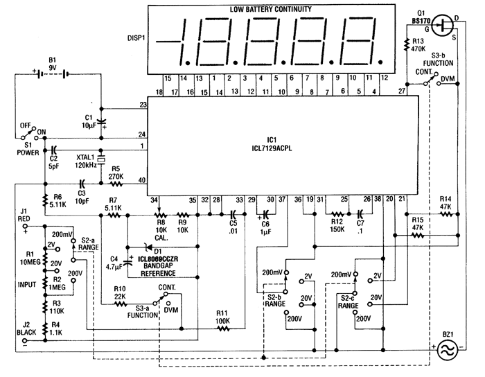
This 4.5-digit digital voltmeter (DVM) circuit is designed around the Maxim ICL7129ACPL analog-to-digital converter (A/D converter) and an LCD driver. It utilizes an ICL8069 CCZR 1.2-V band-gap reference diode for voltage referencing. The switch S2a-b-c allows the selection of...