
15w 12 km range fm transmitter by
The FM transmitter circuit typically consists of several key components, including an oscillator, modulator, and amplifier. The oscillator generates a carrier frequency, which is modulated by the audio input signal. In this circuit, the audio signal is fed into the modulator, where it alters the frequency of the carrier wave according to the amplitude of the input sound.
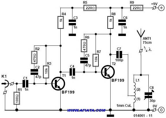
The coil, or inductor, plays a crucial role in determining the operating frequency of the transmitter. By placing the coil directly on the printed circuit board (PCB), the design enhances stability and reduces interference, allowing for more reliable signal transmission. The PCB layout is essential for minimizing parasitic capacitances and inductances that could affect performance.
The P1 potentiometer serves as a variable resistor, enabling the user to adjust the amplitude of the audio signal before it enters the modulator. This feature allows for fine-tuning of the output signal strength, ensuring optimal transmission quality and preventing distortion.
Power supply considerations are also vital in the design of the FM transmitter. A stable voltage source is required to ensure consistent operation of the oscillator and amplifier stages. Additionally, bypass capacitors may be employed to filter out noise from the power supply, further enhancing the performance of the transmitter.
Overall, this basic FM transmitter circuit is an effective solution for short-range audio transmission, suitable for various applications such as personal broadcasting, educational projects, or hobbyist experiments. Proper attention to component selection, PCB layout, and power supply design will contribute to the successful implementation of this circuit.This is a well designed basic FM transmitter that you can easily recive the signals transmitted from this transmitter in a 1-2km range with using a normal FM reciever. Another property of this circuit is that the bobin is placed on the printed circuit board. The input sound`s amplitude can be adjusted by using the P1 potentiometer. 🔗 External reference
Related Circuits
An oscillator-only transmitter appears to be the simplest way to access the radio airwaves; however, it presents several challenges as part of a transmitting and receiving station. The issue of finding an adequate crystal-controlled transmitter for newcomers wishing to...
The circuit was designed to operate a frequency modulation voice transmitter over the FM band within the VHF frequency range. The transmitter is an electronic device. The frequency modulation (FM) voice transmitter circuit operates within the VHF (Very High Frequency)...

An FM and AM transmitter integrated into a compact device utilizing the CD4001 integrated circuit. It broadcasts at 20 MHz for AM and 100 MHz for FM. The described transmitter combines both Frequency Modulation (FM) and Amplitude Modulation (AM) capabilities...
This compact FM transmitter has a range of approximately 50 meters and is designed for hobbyists. With multiple mini-transmitters, users can create a diverse and engaging radio program. The device achieves high frequency stability due to its power supply...
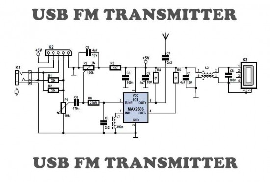
This is a simple USB FM transmitter designed to play audio files from an MP3 player or computer on a standard VHF FM radio. The USB FM transmitter operates by converting audio signals from a digital source, such as an...
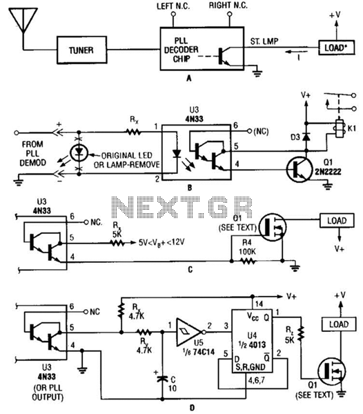
Several possible interface circuits are presented for use with a remote-control transmitter. The circuit labeled A demonstrates a typical FM stereo MUX decoder with a load connected directly to the open-collector output of a TA7343 PLL. The circuit labeled...