
Interfaces For The Remote-Control Transmitter Circuit
The interface circuits serve as versatile solutions for integrating remote-control functionality across various applications.
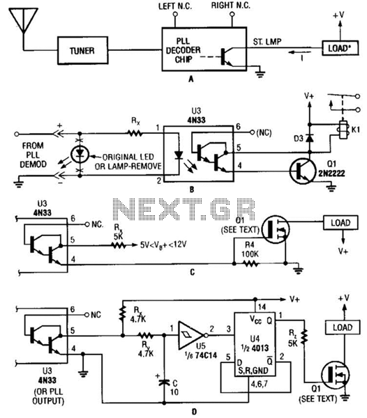
Circuit A utilizes the TA7343 Phase-Locked Loop (PLL) to decode frequency-modulated stereo signals. The open-collector output facilitates direct connection to a load, allowing for the efficient operation of connected devices. This configuration is particularly advantageous for applications requiring minimal component count while maintaining reliable signal processing.
Circuit B employs an optoisolator, specifically designed to provide electrical isolation between the control and output sides, enhancing safety and reducing the risk of noise interference. The optoisolator output drives a 12-V relay coil through a general-purpose transistor, enabling the control of higher voltage devices while protecting the low-voltage control circuit. This arrangement is commonly used in automation systems where isolation is critical.
Circuit C features an N-channel power MOSFET, which is controlled by the output of a 4N33 optoisolator. This configuration allows for efficient switching of high current loads, making it suitable for applications where rapid switching and high efficiency are required. The use of the 4N33 ensures that the control signal remains isolated from the power circuit, thus safeguarding sensitive components.
Lastly, Circuit D implements a toggle flip-flop mechanism, providing a simple yet effective means of achieving push-on/push-off control. This circuit can be utilized in various applications, such as lighting control or motor operation, where the user requires a straightforward method to toggle the state of a device without the need for multiple switches or complex logic.
Overall, these interface circuits exemplify practical solutions for integrating remote-control capabilities, addressing the needs for reliability, safety, and user-friendly operation in electronic designs. Shown here arc several possible interface circuits that can be used with the remote-control transmitter. The one in A illustrates a typical FM stereo MUX decoder with a load connected directly to the open-collector output of a TA7343 PLL.
The circuit in illustrates an optoisolator- coupler output driving a 12-V relay coil via a general-purpose transistor. C shows the gate of an N-channel power MOSFET connected to the output of a 4N33. The final circuit, D, is a toggle flip-flop that allows push-on/push-off control. 🔗 External reference
Related Circuits
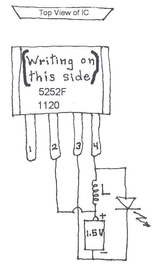
Many Joule Thief circuits traditionally rely on a bulky toroidal inductor that requires careful winding with copper wire. However, there are now compact 4-legged integrated circuits (ICs) available that can perform the same function using only a simple inductor,...

The circuit is a high-power car audio amplifier schematic. It functions as a car audio amplifier using the PA02 and LH0101 integrated circuits (ICs). Each IC delivers an output power of 30W with an 8-ohm impedance. The part list...
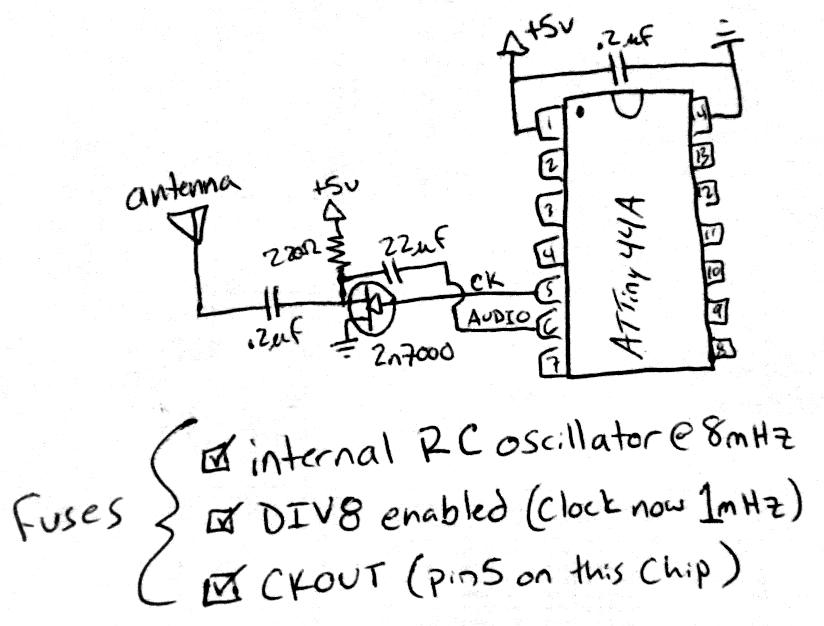
Create a rapid transmitter/receiver pair that can be found in most households. An AM or FM radio system is suitable since it is widely accessible. The design focuses on generating the required radio signal and modulating it effectively. After...
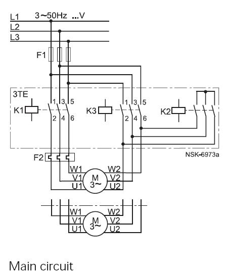
This method reduces starting current and starting torque. The device typically consists of three contactors, an overload relay, and a timer for setting the duration in the star position (starting position). The motor must be delta connected during normal...
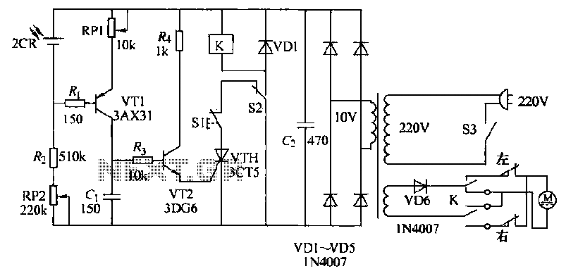
The circuit operates as follows: each morning, light enters the silicon photocell, generating a force that causes transistor VT1 to conduct. As a result, capacitor C charges, leading to an increase in voltage. This rising voltage causes the emitter...
This page shows some methods of track routing control for Stall-Motor type switch machines. The principle method uses a 2 Pole - Multi Position rotary switch while an alternate uses optoisolators and transistors to select the routes. The last...