
USB FM Transmitter circuit
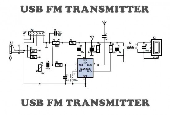
The USB FM transmitter operates by converting audio signals from a digital source, such as an MP3 player or a computer, into radio frequency signals that can be transmitted over the VHF FM band. The key components of the circuit include a USB power supply, an audio input stage, a modulator, and an antenna.
The power supply section typically utilizes a USB connector to provide 5V DC, which is a standard voltage for USB devices. This power is essential for operating the transmitter's circuitry.
The audio input stage receives the audio signal from the MP3 player or computer through a 3.5mm audio jack. This signal is then conditioned for modulation, ensuring that it is at the appropriate level and impedance for the transmitter.
The modulator is the heart of the FM transmitter, where the audio signal is combined with a carrier frequency. This is usually achieved using a frequency modulation technique, which allows the audio signal to vary the frequency of the carrier wave. Commonly, a transistor or an integrated circuit is used for this purpose, which can efficiently modulate the signal while minimizing distortion.
Finally, the antenna is crucial for radiating the modulated signal into the air, allowing it to be picked up by standard VHF FM radios. The design of the antenna can vary, but a simple wire antenna is often sufficient for short-range transmission.
Overall, the USB FM transmitter is a practical solution for wirelessly transmitting audio from digital devices to conventional FM radios, providing a versatile option for audio playback in various settings.Here is a simple USB FM transmitter that could be used to play audio files from an MP3 player or computer on a standard VHF FM radio by connecting it to an. 🔗 External reference
Related Circuits
How to create a hydrogen generator using a 555 timer circuit with Pulse Width Modulation (PWM). This PWM circuit can generate hydrogen on demand. The hydrogen generator circuit utilizing a 555 timer operates by controlling the duty cycle of the...
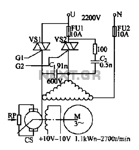
AC voltage is rectified by a bridge (VD1-VD4). A resistor (R1) limits the buck, while diode (VD5) provides clipping. A trapezoidal wave is generated as the trigger circuit for DC voltage and synchronization. When the base of transistor (VT1)...

A passive high-pass filter has been added after the output of the operational amplifier (op-amp) to eliminate DC offset, with the op-amp powered by +12V and the negative supply at 0V. A feedback resistor (Rf) of 500K Ohms is...
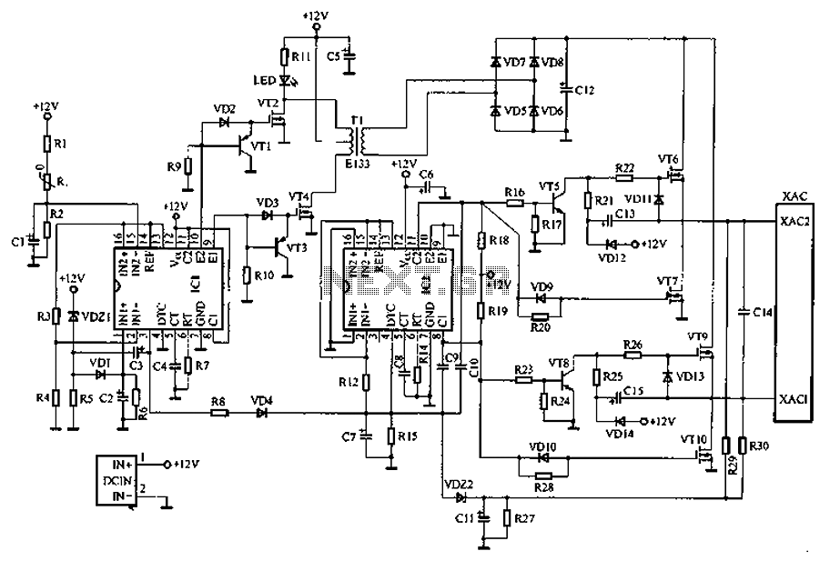
Car inverter specifications include an input voltage range of DC 10V to 14.5V, output voltage of AC 200V to 220V with a tolerance of 10%, output frequency of 50Hz with a tolerance of 5%, and an output power range...
If a negative supply is required for an operational amplifier or if a negative bias voltage is needed while operating from a single supply voltage, such as in battery applications. To generate a negative supply voltage from a single positive...
With this counter you can count laps for example (in conjunction with the Simple light trap). The circuit uses two TTL ICs 74LSxx the series. The left IC is a decimaalteller. The input pulses 14 are counted and converted...
Warning: include(partials/cookie-banner.php): Failed to open stream: Permission denied in /var/www/html/nextgr/view-circuit.php on line 713
Warning: include(): Failed opening 'partials/cookie-banner.php' for inclusion (include_path='.:/usr/share/php') in /var/www/html/nextgr/view-circuit.php on line 713