
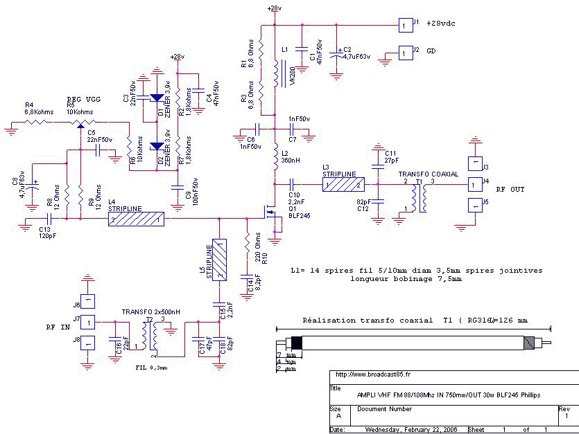
15W - 30W RF Power Amplifier KT922 KT930 KT934
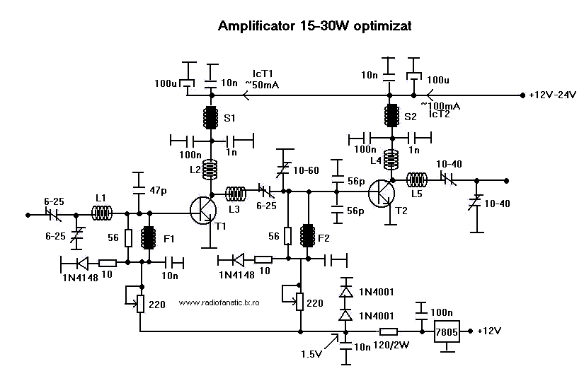
The RF amplifier is a critical component in various communication systems, designed to enhance the strength of radio frequency signals. It operates by taking a weak input signal and increasing its amplitude, thereby making it suitable for further processing or transmission. The performance of the amplifier is influenced by several factors, including the input RF power level, the characteristics of the power supply, and the specific transistor used within the circuit.
In terms of design, the RF amplifier typically includes several key components: the input stage, the amplification stage, and the output stage. The input stage is responsible for receiving the weak RF signal and preparing it for amplification. This may involve impedance matching to ensure maximum power transfer and minimize signal loss. The amplification stage utilizes a transistor, which is the heart of the amplifier, to increase the signal's power. The choice of transistor is crucial, as it affects the amplifier's gain, bandwidth, and overall efficiency.
The output stage of the amplifier is designed to deliver the boosted signal to the next component in the system, which may be an antenna or another stage of processing. It is essential to ensure that the output impedance is matched to the subsequent load to avoid reflections that can degrade performance.
Power supply considerations are also vital, as the amplifier must be adequately powered to achieve the desired performance. The supply voltage and current ratings should match the requirements of the transistor and other circuit components. Additionally, thermal management is important to prevent overheating, which can lead to performance degradation or failure.
Overall, the design and implementation of an RF amplifier require careful consideration of the various parameters to ensure optimal performance in boosting small transmitter signals.This rf amplifier ensure the power you need to boost a small transmitter. Depending of input rf power, power supply and transistor, this amplifier can boos.. 🔗 External reference
Related Circuits
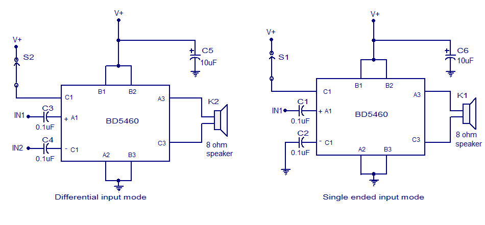
The BD5460 is a low power Class D amplifier that can be utilized in low power applications such as handheld audio devices. The BD5460 does not require an LC filter at the speaker output and can be powered by...
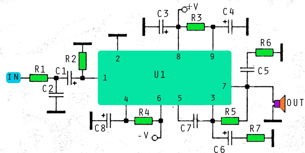
This amplifier circuit utilizes three voltage levels: positive, negative, and ground, with a maximum voltage of approximately 55V DC. The circuit can accommodate several integrated circuits (ICs), including STK 030, 058, 075, 077, 078, 080, 082, 083, 084, and...
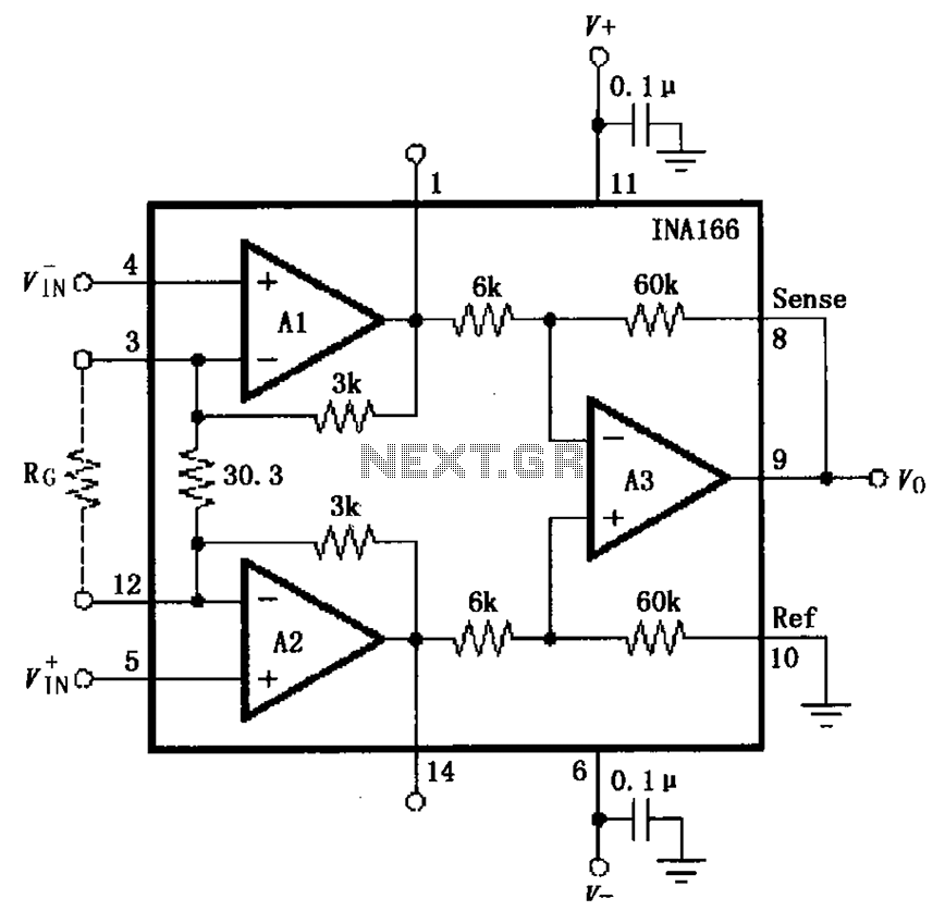
The basic connection circuit for the INA166 includes signal and power connections. A 0.1 µF tantalum capacitor should be used for filtering the chip's power supply terminal, and the PCB layout should be designed to position this capacitor as...
The achievement of this 30 watt amp was thought to take place on a heatsink microprocessor PC. Equipped with its fans, the advantage of this method of cooling was chosen for the fact it is common and not very...
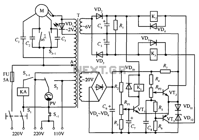
The circuit illustrated in the figure features an automatic voltage regulator (T) that utilizes a servo motor to ensure a constant output voltage. The transistors used are VT1 and VT2 (3DK9C, with a range of 65 to 85) and...
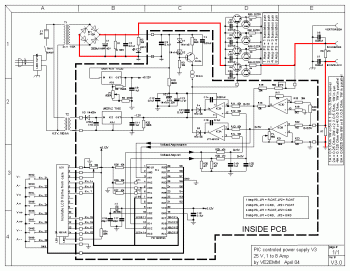
This is a variable power supply controlled by a PIC microcontroller. An LCD display is included in the circuit to show the actual output voltage and current values. A push-button switch is used to adjust the output voltage and...
Warning: include(partials/cookie-banner.php): Failed to open stream: Permission denied in /var/www/html/nextgr/view-circuit.php on line 713
Warning: include(): Failed opening 'partials/cookie-banner.php' for inclusion (include_path='.:/usr/share/php') in /var/www/html/nextgr/view-circuit.php on line 713