
bd5460 class d amplifier circuit
The BD5460 Class D amplifier is designed for efficiency and compactness, making it an excellent choice for portable audio applications. Its ability to operate without an LC filter simplifies the design and reduces the overall component count, making it suitable for space-constrained environments. The amplifier's output capability of 0.8 watts into an 8-ohm load at a nominal voltage of 3.6 V allows for adequate audio performance in small devices, such as portable speakers and handheld gaming consoles.
The integrated standby function is particularly advantageous for battery-operated devices, as it helps to conserve power when the amplifier is not in use. The zero standby current ensures that battery life is maximized, which is critical in portable applications. The built-in short circuit protection and thermal shutdown features provide additional reliability, safeguarding the amplifier from damage due to overload conditions.
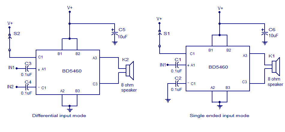
The circuit design includes two configurations for the BD5460, allowing designers to choose between a differential input and a single-ended input setup based on the application's requirements. The use of 0.1 µF decoupling capacitors is crucial for maintaining signal integrity by filtering out unwanted DC offsets and noise, which can affect the amplifier's performance. The 10 µF capacitors serve to stabilize the power supply, ensuring that the amplifier receives clean power for optimal operation.
Shutdown switches S1 and S2 provide a simple method to control the amplifier's operation. By toggling the C1 pin between a high logic level and ground, users can easily switch the amplifier on and off, enhancing user control over the device's power state.
Overall, the BD5460 is a versatile and efficient Class D amplifier that meets the demands of modern low-power audio applications, providing a reliable solution for designers seeking to implement high-quality audio in compact electronic devices.BD5460 is a low power {lass D amplifier that can be employed in low power applications like handheld audio devices. BD5460 doesn`t need an LC filter at the speaker output and can be driven employing a battery, The standby current of BA5460 is usually zero and there`s no switch on / OFF clicks.
The BD5460 can deliver 0. 8 watts into an 8 ohm speaker at 3. 6 V supply voltage. the power supply voltage range is from 2. 5 to 6. 5 V DC. The IC contains a built-in standby function, short circuit protection, thermal shutdown and below voltage lockout. Two class D amplifier circuits using BD5460 are shown here. the first one is a differential input class D amplifier while the second one is a single ended input class D amplifier.
The 0. 1uF capacitors (C1, C2, C3 and C4) are input DC decoupling capacitors. The lower interrupt frequency of the amplifier depends on these capacitors. 10uF capacitors (C5 and C6) are the power supply filters. S1 and S2 are the shutdown switches. Connecting the C1 pin to the high logic can create the IC active and connecting the C1 pin to ground will put the Ic into shutdown mode. 🔗 External reference
Related Circuits
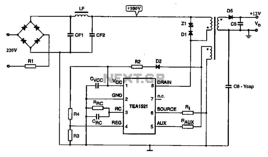
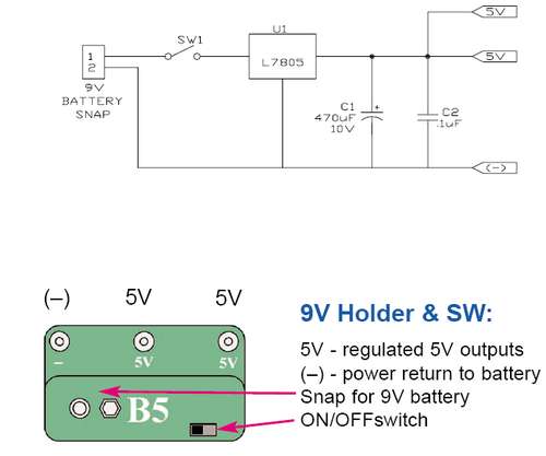
A typical DVD switching power supply circuit is shown in the standby power supply circuit of digital products. It utilizes a switching power supply structure, with the oscillation switch IC EA1623 providing oscillation pulses to the transformer. The secondary...
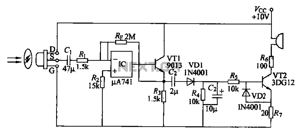
A simple burglar alarm circuit utilizes a pyroelectric sensor (IRA-E100SZI). When human movement is detected, it triggers an electric buzzer alarm. The sensor receives signals through an AC amplifier, which is then converted by a rectifier circuit into a...
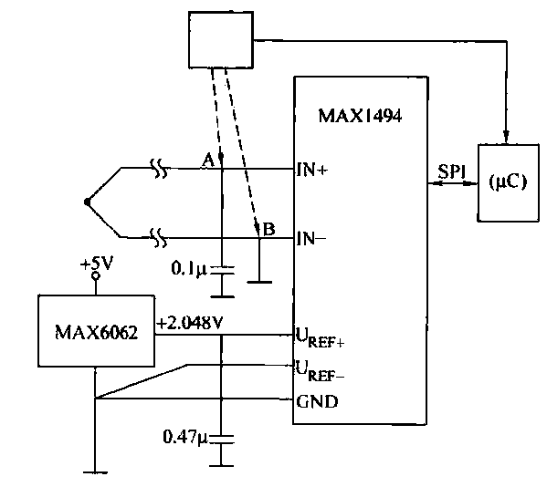
The circuit consists of the MAX1494 and a thermocouple temperature measurement system. The MAX1494 is terminated at 1N GND 5-32. An external temperature sensor, such as the DS75, can be utilized for junction temperature compensation. The MAX1494 employs an...
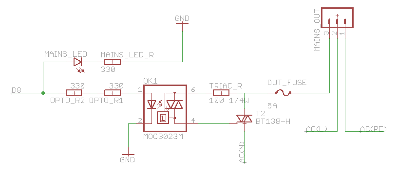
The heatsink on the triac is somewhat unclear. A maximum value of 10°C/W has been calculated, which raises concerns. The calculation is as follows: (maximum temperature - room temperature) / (maximum on-stage voltage * (milliamps / voltage) - junction-to-base...
1. A robot may not injure a human being or, through inaction, allow a human being to come to harm. 2. A robot must obey the orders given to it by human beings, except where such orders would conflict...
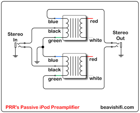
Construct a basic passive preamplifier for use with an iPod, Zune, or other portable media players. This device is particularly useful for enhancing audio quality in a car environment. A passive preamplifier is a circuit designed to amplify audio signals...
Warning: include(partials/cookie-banner.php): Failed to open stream: Permission denied in /var/www/html/nextgr/view-circuit.php on line 713
Warning: include(): Failed opening 'partials/cookie-banner.php' for inclusion (include_path='.:/usr/share/php') in /var/www/html/nextgr/view-circuit.php on line 713