
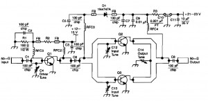
30 Watt FM Linear amplifier with Mosfet BLF245

The described 30-watt amplifier is designed for VHF FM and AM operations, specifically tuned for a frequency range of 88 to 108 MHz. The amplifier utilizes a Class AB amplification mode, which provides a balance between linearity and efficiency, making it suitable for RF applications. The construction involves a double-sided printed circuit board (PCB) made from glass epoxy, with a thickness of 0.8 mm, allowing for a compact design while maintaining structural integrity.
The PCB dimensions are specified to be 73 mm in width and 63 mm in height, accommodating the necessary strip-line configurations for RF signal integrity. The design incorporates ground planes, which can be constructed using either copper pours or resistor leg crossings, ensuring effective grounding and minimizing noise interference.
Thermal management is a critical aspect, and the amplifier is designed to be mounted on a heatsink with fans, providing adequate cooling during operation. The heatsink should have pre-drilled holes for M3 screws to secure the PCB and the power transistor (BLF245). Proper thermal paste application is essential to ensure efficient heat transfer from the transistor to the heatsink.
The circuit includes various SMD components, including capacitors, resistors, and inductors, which are to be placed according to a specified order to facilitate soldering and assembly. Care must be taken to ensure that all components are correctly oriented, particularly polarized components like capacitors and diodes.
The amplifier's performance can be tested by connecting it to a 50-ohm dummy load and measuring the output power with a wattmeter. Initial adjustments of the potentiometer should be made to achieve a specified voltage at the transistor's drain, followed by gradual increases in input power to verify the amplifier's output capabilities without exceeding safe operational limits.
Overall, this amplifier design emphasizes efficient cooling, precise component placement, and rigorous testing to achieve reliable performance in VHF applications.The achievement of this 30 watt amp was thought to take place on a heatsink microprocessor PC. Equipped with its fans, the advantage of this method of cooling was chosen for the fact it is common and not very expensive. The size of the printed circuit will adapt quite easily to the type of sink that you have available, nine if possible, because often, those of recovery, the fans have already lived and the price of a new model remains very affordable.
The amplification mode is class AB. Below is a description of the mounting frame. Ground planes are made of carnations, but it is also possible to achieve with simple crossings "legs of resistors," for example .. The circuit will be constructed from glass epoxy double-sided, 0.8 mm thick. The dimensions of the circuit must be respected at best, due to the presence of lines granted "strip-line.
These dimensions are 73 mm wide and 63 mm in height. It is preferable to make the holes and threads of the sink before starting to wire the map. The holes correspond to the four struts holding the PCB and the two central holes in the fixing of the transistor. The heatsink and printed circuit board is assembled with a few slices to ensure the height relative to the fixing of the transistor.
In my case, four rounds were necessary. The threads are boring M3.Après format, check that the holes overlap and are centered. Pre-installation, installation of rivets. To do this, I use a needle and a hammer, no special tools! After installation, I run the weld duplex. The rivets can be replaced by bushings "legs of resistance" welded on both sides, the result will be the same! The rivets and welding applied! That's what it gives the copper side, we need a soldering iron hot and powerful! The placement of SMD components. Start with the resistors and capacitors, diodes and then finish by chemical and potentiometer adjustable so that the few crossings "+28 V, the RF output.
For better stabilized circuit for setting CMS, attach it to the sink, the whole move less! From now on, you can ask the BLF245, start with the set with two M3 screws after putting the thermal paste and tighten moderately. Do not take the wrong direction, the beveled side "drain" on the side of the capacity output. Do not forget precisely this ability! Finish by laying the coils, toroid ferrite and coaxial line. See details below! The choke can be a VK200 no impact on operations. Details on the coaxial line and the ferrite core. See the diagram at the top of the page for the dimensions of this line. For the torus, see the nomenclature of the components. Stiffen the self with a bit of Araldite. Your amplifier is now finished! VHF FM AMPLIFIER IN 88/108Mhz 750mw/OUT 30w Philips BLF245 October 22, 2006 http://www.broadcast85.fr Item Quantity Reference Value components ______________________________________________________________________ 1 2 C1, C4 47nF50v 2 2 C2, C8 4.7 uF63v 3 2 C3, C5 22nF50v 4 2 C6, C7 1nF50v 5 1 C9 100nF50v 6 2 C10, C15 2.2 nF 7 1 C11 27pF 8 2 C12, C18 82pF 9 1 C13 120pF 10 1 C14 8.2 pF 11 1 C16 22pF 12 1 C17 47pF 13 2 D1, D2 Zener 3.9 v 14 8 J1, J2, J3, J4, J5, J6, J7, J8 PCB pads 15 1 L1 2.4 uH 16 1 L2 360nH 17 3 L3, L4, L5 STRIP-LINE 18 1 Q1 BLF245 19 2 R1, R3 5.6 Ohms 20 2 R2, R7 1.8 Kohm 21 1 R4 6.8 Kohm 22 2 R5, R6 10kohms 23 2 R8, R9 12 Ohms 24 1 R10 220 Ohm 25 1 T1 COAXIAL TRANSFORMERS 26 1 T2 TRANSFORMERS 2x500nH All components are SMD C10 2.2 nF capacitor for high voltage resistance type series Vislay VJ1812 1kV available in RS.
The coaxial transformer is the RG316 "See" Ferrite transformer T2 is available in RS-ref 467-3573 per pack of 10 This ferrite bead is wound with enamelled copper wire of 0.2 mm. Midpoint each end to the value of self will be 500nH. L2 14 turns over 0.5 mm 3.5 mm contiguous turns L1 VK200 C11 and C12 are the type ATC100B Development of the amp Once the card is fully wired, the transistor in place and the normal controls made, and weld quality control errors, connect the amplifier to a 50 ohm dummy load by inserting a reflectometer wattmeter.
Turn on the whole under 28v, adjust the potentiometer to obtain a voltage of 3.5 V on the spoils of the BLF245 . Excite with less power "realize the modification of the synthesizer to vary its power." Gently step in checking the power meter needle on 98mhz, it should come out about thirty watts for only 500mw of excitement.
Check the operation of 88 to 108MHz, the gain can vary more or less! Do not exceed 30 watts or even be limited to 25 watts per security! 🔗 External reference
Related Circuits

This is a 2W RF amplifier circuit built with the power MOSFET LF2810A. The schematic of the microstrip single-stage RF amplifier is shown in Figure A. The amplifier utilizes the M/A-Com LF2810A MOSFET, which is rated for a power...
The Poppet is a half-watt AM transmitter designed by Mr. Doug Gibson of England. The original design was published in issue 84 of SPRAT, the newsletter of the GQRP Club. The version presented here incorporates modifications suggested by Steve...
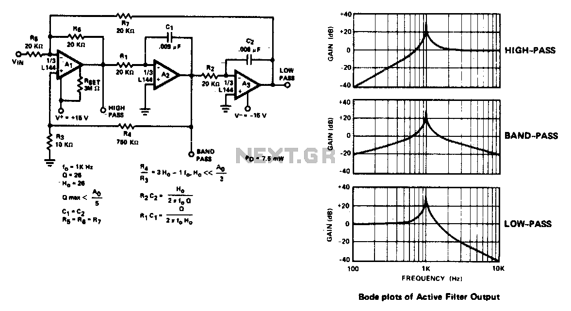
The active filter is a state variable filter with bandpass, high-pass, and low-pass outputs. It is a classical analog computer method of implementing a filter using three amplifiers and only two capacitors. The state variable filter is a versatile circuit...
This RF amplifier circuit delivers a power output of 4 Watts at a frequency of 900 MHz. It utilizes Wilkinson power dividers in the base and collector circuits of transistors Q2 and Q3. Two SD1853 driver application transistors are...
The AD537 is a monolithic voltage-to-frequency (V-F) converter that includes an input amplifier, a precision oscillator system, an accurate internal reference generator, and a high-current output stage. A single external resistor-capacitor (RC) network is sufficient to configure any full-scale...
This article is intended for individuals interested in constructing their own car amplifier. The fundamental calculations involved will be discussed below. Understanding these concepts will enable the construction of a car amplifier independently. The complexity of designing a car...