
16 G— 2 LCD Volt Meter & Ampere Meter With PIC Schematic Diagram

The circuit design incorporates the PIC16F876A microcontroller, which is central to processing the measurements of voltage and current. The microcontroller features multiple analog-to-digital converters (ADCs) that facilitate the conversion of analog voltage signals into digital data for processing. This data can then be displayed on the 16x2 LCD, which serves as the user interface for reading the measurements.
The voltmeter section of the circuit typically consists of a voltage divider network to scale down high voltages to levels suitable for the microcontroller’s ADC. Resistors in the divider are selected based on the expected input voltage range to ensure accurate readings. The ammeter section often employs a shunt resistor in series with the load, where the voltage drop across the shunt is measured and converted to a current reading using Ohm’s law.
The LCD display is interfaced with the PIC microcontroller using a parallel communication method, allowing for the transmission of character data to be displayed. The microcontroller executes a program that continuously reads the ADC values corresponding to the voltage and current, processes these values, and formats them for display.
Power supply considerations are crucial; the circuit may require a regulated power source to ensure the PIC and the display operate reliably. The design may also include filtering capacitors to stabilize the power supply and reduce noise, which is essential for accurate measurements.
In summary, this circuit effectively combines the capabilities of the PIC16F876A microcontroller with a 16x2 LCD display to provide real-time measurement of voltage and current, making it a valuable tool for various electronic applications.Volt meters & ampere meter with PIC can be used to measure voltage and current simultaneously. The series of volt meters & ampere meter with PIC16F876A PIC is used as a data processor voltage and current are measured. This circuit uses the viewer in the form of 16 G— 2 LCD used for the data display voltage and current measurements.
In the article volt meter and ampere meter with PIC are discussed kerannya limited to devices only. More detail can be seen from the image sequence volt meter and ampere meter with PIC below. You are reading the Circuits of 16 G— 2 LCD Volt Meter & Ampere Meter With PIC And this circuit permalink url it is 🔗 External reference
Related Circuits

This temperature meter utilizes the precision micro power centigrade sensor IC LM35. The output voltage of the IC is linearly proportional to 10 mV per degree centigrade. The LM35 temperature sensor is a versatile and widely used device in electronic...
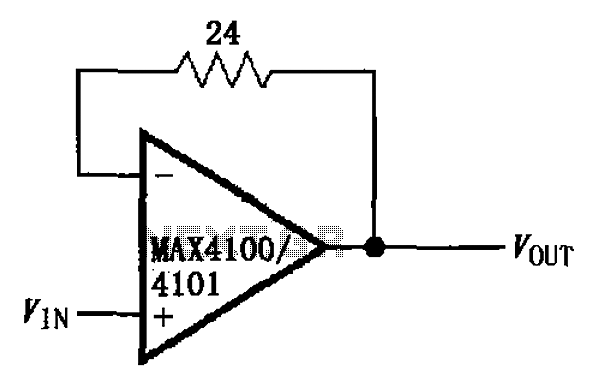
The circuit illustrated is a unit gain buffer circuit utilizing the MAX4100/4101 operational amplifiers. It incorporates a small resistor (24 ohms) within the feedback loop of the amplifier, thereby establishing a unity gain buffer. This configuration maximizes the bandwidth...
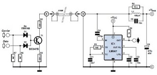
This circuit was designed to transmit commands over an LNB coaxial cable. An LNB (Low-Noise Block downconverter) is commonly used for satellite TV reception and is positioned at the focal point of a satellite dish. The circuit generates a...
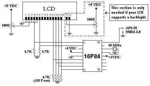
This is a project that I started back late 2003 when I just starting to learn PIC programming. I wanted to building something that actually did something useful. This project is based on a PIC16F84. I actually came up...
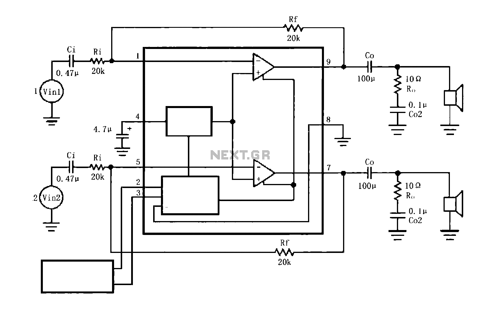
The circuit illustrated is a typical configuration for the LM4916 two-channel amplifier. The left and right channel audio signals are fed into the LM4916, which amplifies them internally. The output is then delivered through a coupling capacitor (Co) to...
This precise one-pulse-per-second clock is constructed using a few common components and is driven by a 50 or 60 Hertz mains supply, without any direct connection to it. It produces a beep or metronome-like click and/or a visible flash...