
LNB Cable Data Transceiver Circuit Schematic Diagram

This circuit operates by utilizing a modulated signal to facilitate communication over the coaxial cable used in satellite systems. The LNB serves as a critical component, converting high-frequency satellite signals into lower frequency signals suitable for further processing. The LM567 tone decoder is pivotal for detecting the modulated signal, providing a reliable means to decode the transmitted commands.
The combination of diodes D1 and D2 allows for the ORing of the data and carrier signals, ensuring that both signals can coexist on the same bus without interference. Transformer T1 is essential for regulating the current flow, with its output dependent on the resistance value of R3, allowing for precise control over the signal strength.
The resonance circuit formed by L1 and C5 is crucial for maintaining signal integrity at the carrier frequency, which is essential for effective communication. The low impedance bypass provided by C6 minimizes signal loss and ensures that the current flow remains stable, which is vital for the performance of the entire circuit.
The coupling of IC1 to the bus via C4 allows for effective signal detection, while the configuration of R1, C1, and C2 enables fine-tuning of the decoder's operational parameters, ensuring optimal performance across varying data frequencies. The output filter C3 is tailored to the specific data frequency, further enhancing the circuit's capability to filter out unwanted noise.
The design stipulates that the carrier frequency must significantly exceed the data frequency, adhering to the guidelines set forth in the LM567 datasheet to ensure reliable operation. The overall architecture of the circuit, with the inclusion of R5 as a load for IC1, guarantees that the output remains in phase with the data signal, which is crucial for maintaining the integrity of the transmitted commands.
In summary, this circuit exemplifies a sophisticated approach to command transmission over LNB coaxial cables, utilizing well-established components and principles to achieve effective communication in satellite TV applications. The design's flexibility allows for implementation in various scenarios, making it a valuable solution in the field of satellite communications.This circuit was designed and used to transmit commands over LNB coaxial cable. An LNB (or LNC) is a low-noise block downconverter typically used for satellite TV reception. It`s fitted in the focal point of a satellite dish. [LNB Cable Data Transceiver Circuit] The circuit is based on generating a modulated signal on the bus which can be decoded by a tone decoder IC like the familiar LM567 from National Semiconductor. Data and carrier signals are ORed using D1 and D2. T1 acts as a current source whose current depends mainly on the value of R3. L1 and C5 form a (damped) resonance circuit for the centre frequency of the carrier. C6 acts as a very low impedance bypass, so the impedance seen by T1 at the carrier frequency equals roughly R4. As the current passes through R4, the voltage generated across it can be detected by IC1 which has its input coupled to the bus via C4.
The low DC resistance of inductor L1 allows current to flow to the circuitry connected to the bus. Components R1 and C1 control the centre frequency of the decoder, and C2 the bandwidth. Relevant formulas may be found in the LM567 datasheets. C3 is output filter and its value depends on the data` frequency. In accordance to what`s found in the LM567 datasheet, the carrier frequency must be at least 20 times higher than the frequency of the data` signal. The maximum detectable carrier frequency is about 500 kHz. R5 is just a load for IC1, whose output is signal in phase with data`. The Carrier frequency can be generated using any simple square wave generator. In the author`s application, the carrier frequency was 100 kHz with 1200 bps data, both generated by a microcontroller.
The transmitter and receiver were installed at each side of the LNB cable to create a half-duplex transceiver. Author: Sajjad Moosavi. 🔗 External reference
Related Circuits
The Arduino Uno has adequate memory and ports, but efficient programming is necessary to store settings in memory. The Mega version offers increased memory and ports. The Shako valve operates on 24 volts DC; however, 12 volts is preferred...
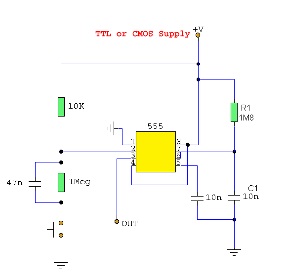
The 555 circuit can be re-triggered if the input is held low for a duration longer than the output pulse. To prevent this from occurring, an additional timing circuit has been incorporated, consisting of a 1 Megohm resistor and...
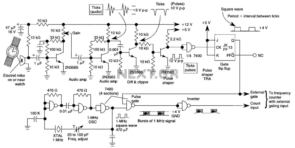
This circuit adapts a frequency counter to measure intervals. It was originally utilized as a shutter speed checker for photographic applications. The watch ticks are clipped, shaped, and formed into a square wave. This square wave is employed to...
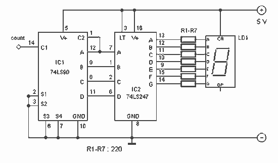
With this counter you can count laps for example (in conjunction with the Simple light trap). The circuit uses two TTL ICs 74LSxx the series. The left IC is a decimaalteller. The input pulses 14 are counted and converted...
The circuit described can connect two telephones in parallel and function as a two-line intercom. Typically, a single telephone is connected to a telephone line. When another telephone is needed at a distance, a parallel line is utilized for...
If residing in a cold climate, it is reassuring to confirm the functionality of an engine-block heater. This device indicates whether the heater is operational. To use, connect PL1 to a power outlet; the NE1 indicator should illuminate. Next,...